1
Modern capabilities of 3D technologies make it possible to present the process of operation of many logistics functions of an enterprise. However, the choice of technology is not always obvious. This article provides a description and analysis of various technological solutions for presenting graphic information. Graphic libraries OpenGL, Direct 3D, JAVA3D and JavaOpenGL are considered. Web technologies for creating three-dimensional scenes are presented, such as Alternativa 3D, Unity 3D, WebGL, VRML. A comparative analysis of the considered technologies has been performed. When comparing technologies, the choice was made in favor of JavaOpenGL as a more flexible and cross-platform visualization solution within the framework of the developed system. The necessary results of interaction of the developed 3D service with the existing system are presented. The choice of visualization tool was made taking into account the criteria of the developed tracking, control, analysis and optimization system for the full production cycle of metallurgical products.
logistics processes
graphic information
visualization
3D technology
1. Brief overview of the virtual reality modeling language VRML // Electronic resource. Access mode: http://litvinuke.hut.ru/articles/vrml.htm (date accessed 10.10.2013).
2. What is DirectX // Electronic resource. Access mode: http://www.dvfu.ru/meteo/PC/directx.htm (access date 10.10.2013).
3. Virtual reality modeling language VRML // Electronic resource. Access mode: http://el-izdanie.narod.ru/gl7/7-7.htm (access date 10.10.2013).
4. Alternativa 3D // Electronic resource. Access mode: http://alternativaplatform.com/ru/technologies/alternativa3d/ (access date 10/10/2013).
5. 3D on the web - choice of technology // Electronic resource. Access mode: http://habrahabr.ru/post/149025/ (access date 10.10.2013).
6. Unity 3D // electronic resource. Access mode: http://www.unity3d.ru/
7. Java3D TM Graphics // electronic resource. Access mode: http://www.java3d.org/ (accessed 10/10/2013).
8. Kai Ruhl. JOGL (JavaOpenGL) Tutorial // Electronic resource. Access mode: http://www.land-of-kain.de/docs/jogl/ (accessed 10.10.2013).
9. The Industry's Foundation for High Performance Graphics // Electronic resource. Access mode: http://www.opengl.org/ (access date 10/10/2013).
10. WebGL // Electronic resource. Access mode: http://www.khronos.org/webgl/ (accessed 10/10/2013).
Introduction
At the Department of Information Technologies of the Federal State Autonomous Educational Institution of Higher Professional Education "Ural Federal University named after the first President of Russia B. N. Yeltsin" work is underway on the project: "Development of an automated system for tracking, control, modeling, analysis and optimization of the full cycle of production of metallurgical products (AS VMP) based on the creation and integration mathematical models of technological, logistics and business processes of an enterprise.” Project initiator: I-Teco CJSC (Moscow).
The automated system being developed should include the following functions:
- collection and storage of technological information and quality indicators in relation to the unit of production, time and place of processing;
- visualization of data for a wide range of specialists and managers;
- automatic detection of deviations of parameters from pre-selected criteria;
- statistical tool for analyzing deviations and developing corrective actions to eliminate the causes of deviations;
- analysis of end-to-end technology and development of relationships between technological parameters and product quality parameters in order to adjust the existing technology.
The list of these functions can be implemented using different software, but it is obvious that the process visualization module must be integrated with the data warehouse.
Computer visualization of an enterprise's production processes becomes relevant when production occupies large areas or is geographically divided. In the case of metallurgical production, we have a plant whose production area is more than 10 thousand square meters. m. Obviously, even monitoring the movement of products can cause a problem.
Statement of the problem
Due to the intensive development of computer graphics, the use of three-dimensional models to solve various scientific and industrial problems has recently become widespread. This list also includes the management of logistics processes. Logistics functions such as warehousing, supply management, inventory and purchasing, transportation management, and optimization of vehicle routes are usually controlled by some kind of modeling system. Graphic display of warehouses, production facilities, and products using 3D visualization will undoubtedly allow you to better navigate in space. The user of the system will have the opportunity to observe the movement of production objects in the same way as in real space, and make management decisions thanks to auxiliary visual aids (Fig. 1).
Rice. 1. 3D visualization of the workshop
To create a 3D graphic service, it is necessary to consider possible tools and technologies that allow you to visualize objects in three-dimensional space. The technology was selected based on the following criteria:
- Possibility of integrating the visualization module with an existing system.
- Cross-platform support.
- Browser support.
- Visualization performance, taking into account the variety of graphic elements used.
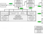
In its simplest form, the structure of the system can be represented in the form of a diagram (Fig. 2). VMP AS simulation modeling software places the model design result in a data warehouse (DW) selected by the customer. The data storage can be either a file resource or a relational database. The data warehouse receives information on the execution of enterprise processes. To visualize the model, a three-tier architecture is used on the WEB platform, which allows you to flexibly change and update the model display tools, the simulation data access protocol and the operating algorithm without changing the requirements for client devices.

Rice. 2. Place of the 3D model in the system structure
First, let's look at existing graphics libraries that work with 3D graphics at a low level of abstraction.
Graphics libraries
Open Graphics Library is a graphics standard that supports a low-level programming model and provides extensive capabilities in 3D graphics modeling. It is one of the most popular graphics standards around the world. Programs written using OpenGL can be transferred to almost any platform, while obtaining the same result, be it a graphics station or a supercomputer. OpenGL frees the programmer from writing programs for specific hardware. If the device supports a certain function, then this function is performed in hardware; if not, then the library performs it in software.
The Direct3D graphics library is part of the DirectX API and is a programming interface for 3D graphics output. Direct X is a set of interfaces designed to solve problems associated with programming under the Microsoft Windows operating system. Almost all parts of the DirectX API are collections of COM-compatible objects. One of the most important features of Direct3D is its transparent access to graphics accelerators. If the hardware platform does not support a feature, Direct3D implements its equivalent in software. In addition, Direct3D enables fast software rendering using a complete 3D graphics rendering pipeline.
JavaSoft has implemented 3D capabilities in Java (Java 3D) by creating its own library and linking it to standard OpenGL and DirectX tools. But the programming interface for 3D applications in Java is significantly different from OpenGL, approaching that of the high-level OpenInventor library. The library is conventionally divided into a basic part (javax.media.j3d, javax.vecmath) and an auxiliary part (com.sun.j3d.audioengines, com.sun.j3d.loaders, com.sun.j3d.utils). The first serves as the foundation of the Java 3D API, determines its technical capabilities and specifies the mechanism for interaction of objects. The second is an add-on implemented using base classes, facilitating the use of the most frequently used operations and expanding the developer's capabilities.
The JavaOpenGL Library (JOGL) is a direct binding of OpenGL functionality to the Java programming language. It is a reference implementation of the JSR-231 specification (JavaBindingstoOpenGL). JOGL gives the programmer access to all the capabilities of the OpenGL API and to two major OpenGL extensions. JOGL differs from other OpenGL shells in that it provides the programmer with the ability to work with the OpenGL API by accessing OpenGL commands through calls to the corresponding methods with the types of arguments familiar to the Java developer. The low level of abstraction of JOGL makes it possible to build programs that are quite efficient in terms of execution speed, but complicates the programming process compared to shells for OpenGL for Java (for example, such as Java3D).
Web technologies for creating three-dimensional scenes
In accordance with the technical requirements and within the framework of the problem being solved, to ensure cross-platform conditions, it is more appropriate to consider existing Web technologies for three-dimensional modeling.
VRML (VirtualRealityModelingLanguage) is an open standard developed by ISO (International Organization for Standardization). The first three-dimensional modeling language developed for the Web, it can be classified as a scripting language. The language is designed to describe three-dimensional objects and design 3D worlds. The VRML language allows you to create complex 3D scenes using text commands. These commands describe polygonal objects and special effects to simulate lighting, environments, and to add realism to an image.
Alternativa3D technology is designed to display three-dimensional graphics in the Flash Player environment. The Alternativa3D 8 graphics engine was developed by Alternativa Platform for use in its own projects. The capabilities of Alternativa3D are multifaceted and varied, and applications range from creating fully three-dimensional websites on the Internet to developing multiplayer browser games and projects for social networks in 3D. Visualization occurs through the Direct3D and OpenGL libraries, or the SwiftShader software emulator, which means it can work on all popular operating systems and devices, including PCs, laptops, netbooks and mobile platforms, including Android. Alternativa3D's special binary format reduces the amount of data required to transfer over the network, which speeds up loading the scene into the engine. Models are exported to this format from the 3DSMax package using the appropriate plugin.
WebGL (Web-basedGraphicsLibrary) is a software library for the JavaScript programming language that allows you to create interactive 3D graphics in JavaScript that operate in a wide range of compatible web browsers. By using low-level support for the OpenGL library, some WebGL code can be executed directly on video cards. WebGL is based on the OpenGL API, and with some convention we can say that WebGL is a “binding” of OpenGL for JavaScript. WebGL focuses on the set of capabilities provided by OpenGL ES 2.0, which allows it to be used on a wide range of equipment: both on desktops and on mobile platforms. Like OpenGL, WebGL is a low-level API, and in order to create projects using it directly, you need to have a fairly good understanding of many of the more advanced aspects of 3D graphics. Currently, WebGL is already supported by the Google Chrome, Mozilla Firefox and Opera browsers for Windows, Linux and MacOS, and the Firefox for Android browser. Safari builds for MacOS have the option to enable WebGL support.
Unity 3D is a multi-platform tool for developing 2D and 3D applications running on Windows and OSX operating systems. Applications created with Unity run on Windows, OSX, Android, AppleiOS, Linux operating systems, as well as on Wii, PlayStation 3 and Xbox 360 game consoles.
The Unity game engine is adapted to the development environment, which allows you to render the scene directly in the editor. Import from a large number of formats is supported. Network support is built-in.
Technology Analysis
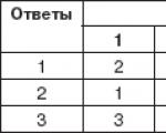
As a result of the analysis of the technologies considered, a comparative table was compiled (Table 1). The table shows that only Web technologies and the JOGL library satisfy all the criteria.
Table 1. Comparison of technologies
|
Development Tool
|
Work under Windows OS
|
Work under Linux OS
|
Web support
|
Integrated Development Environment
|
Mobile platform support
|
|
|
|
|
|
All programming languages
|
|
|
|
|
|
|
|
|
|
|
|
|
|
|
|
|
|
|
|
|
|
|
|
|
|
|
|
|
|
|
|
|
|
|
|
|
|
|
|
|
|
Editor Unity3D, C#, JavaScript, Boo
|
|
|
|
|
|
|
VRML editor
|
|
In development tools such as OpenGL ES (OpenGL for Embedded Systems) and Direct3D, there is support for Mobile platforms, but they are not taken into account in the table, since they are subsets and varieties of OpenGL and Direct 3D.
Research work on 3D modeling technologies was carried out with the goal of finding the most suitable tool for three-dimensional visualization of production and logistics processes of a metallurgical enterprise.
As a result, graphics libraries OpenGL and Direct 3D, JAVA 3D and Java OpenGL were considered. When comparing these libraries, the choice was made in favor of Java OpenGL as a more flexible and cross-platform visualization solution within the framework of the developed system.
The use of the high-level language JAVA for developing a simulation modeling tool and the availability of high-quality implementation of three-dimensional visualization tools in JAVA give reasons for choosing this language as the main tool for developing a visualization module for the Linux OS.
In accordance with the technical requirements and within the framework of the problem being solved, to ensure cross-platform conditions, it was concluded that it is advisable to consider Web technologies for three-dimensional modeling. Analysis of Web technologies for creating three-dimensional scenes Alternativa3D, Unity 3D, WebGL and VRML showed that the use of ready-made engines (for example, Unity 3D) also has prospects for integration with the developed AS VMP modules. Particularly noteworthy is the WebGL visualization technology, which is supported by most modern browsers: GoogleChrome, Opera, Mozilla.
The work was performed under contract No. 02.G25.31.0055 (project 2012-218-03-167).
Reviewers:
Shabunin S.N., Doctor of Technical Sciences, Professor, Department of High-Frequency Radio Communications and Television, Federal State Autonomous Educational Institution of Higher Professional Education "Ural Federal University named after. the first President of Russia B.N. Yeltsin", Yekaterinburg.
Dorosinsky L.G., Doctor of Technical Sciences, Professor, Head of the Department of Information Technologies, Ural Federal University. the first President of Russia B.N. Yeltsin", Yekaterinburg.
Bibliographic link
Dmitriev I.L., Papulovskaya N.V., Aksenov K.A., Kamelsky V.D. 3D VISUALIZATION OF PRODUCTION AND LOGISTICS PROCESSES: CHOICE OF DEVELOPMENT TOOL // Modern problems of science and education. – 2014. – No. 2.;
URL: http://science-education.ru/ru/article/view?id=12657 (access date: 02/03/2020). We bring to your attention magazines published by the publishing house "Academy of Natural Sciences" Approved and put into effect by order of the Federal Agency for Technical Regulation and Metrology dated March 31, 2016 N 232-st
National standard of the Russian Federation GOST R 56907-2016
"LEAN PRODUCTION. VISUALIZATION"
Lean Production. Visualization
OKS 03.120.10
Introduced for the first time
Reissue. May 2017
Preface
1 Developed by the Federal State Budgetary Educational Institution of Higher Education "Moscow Automobile and Highway State Technical University (MADI)" together with a working group consisting of: FSBEI HPE "ASU", ANO "Academy of Management", OJSC "Amur Shipbuilding Plant", LLC "BaltSpetsSplav" ", Russian Helicopters JSC, Vyksa Metallurgical Plant JSC, Gazpromneft-snabzhenie LLC, KnAF Sukhoi Civil Aircraft JSC, IL JSC, Irkut Corporation JSC, Kazan National Research Technical University named after A. .N. Tupolev-KAI" (KNITU-KAI), OJSC "KAMAZ", LLC "LinSoft", PJSC "Company "Sukhoi", JSC "Lada-Image", Ministry of Industry and Trade of the Republic of Tatarstan, LLC "National Management Systems" , OJSC NLMK, PJSC Research and Production Corporation United Carriage Company (PJSC NPK UWC), OJSC Baltic Shipbuilding Plant Yantar, PJSC UAC; GC "Orgprom", LLC "PenzTISIZ", State Atomic Energy Corporation "Rosatom", JSC "Russian Railways", JSC "RSK "MiG", MOO "Union of the Thrifty", CJSC "Center "Priority", Udmurt State University, JSC " Cherkizovsky MPZ"
2 Introduced by the Technical Committee for Standardization TC 076 "Management Systems"
3 Approved and put into effect by Order of the Federal Agency for Technical Regulation and Metrology dated March 31, 2016 N 232-st
4 Introduced for the first time
5 Reissue. May 2017
Introduction
This standard was developed on the basis of the best experience accumulated by organizations of the Russian Federation and taking into account the best world practice in the use of visualization - the lean manufacturing method (hereinafter referred to as LP).
This standard is designed for use in any organization that has decided to improve performance through the use of visualization.
This standard was developed using the regulatory framework GOST R 56020 and GOST R 56407.
1 Application area
This standard is intended for use in lean manufacturing management systems and other management systems and is applicable to all organizations, regardless of their size, form of ownership and type of activity.
This standard is a guide to the use of a visualization method based on the recommended principles of BP in accordance with GOST R 56407.
2 Normative references
This standard uses normative references to the following standards:
GOST R 56020-2014 Lean manufacturing. Fundamentals and Vocabulary
GOST R 56407-2015 Lean manufacturing. Basic methods and tools
GOST R 12.4.026-2001 System of occupational safety standards. Signal colors, safety signs and signal markings. Purpose and rules of use. General technical requirements and characteristics
GOST R 56906-2016 Lean manufacturing. Workspace organization (5S)
Note - When using this standard, it is advisable to check the validity of reference standards and classifiers in the public information system - on the official website of the Federal Agency for Technical Regulation and Metrology on the Internet or using the annual information index "National Standards", which was published as of January 1 of the current year, and according to the releases of the monthly information index "National Standards" for the current year. If an undated reference standard is replaced, it is recommended that the current version of that standard be used, taking into account any changes made to that version. If a dated reference standard is replaced, it is recommended to use the version of that standard with the year of approval (adoption) indicated above. If, after the approval of this standard, a change is made to the referenced standard to which a dated reference is made that affects the provision referred to, it is recommended that that provision be applied without regard to that change. If the reference standard is canceled without replacement, then the provision in which a reference to it is given is recommended to be applied in the part that does not affect this reference.
3 Terms and definitions
This standard uses terms according to GOST R 56020 and GOST R 56407, as well as the following term with the corresponding definition:
3.3 visualization method: A systematized set of actions for visualizing objects.
4 Basic provisions
4.1 Purpose and objectives of visualization
The visualization method is used in an organization for the purpose of presenting information in a visual form (drawing, photograph, graph, chart, diagram, table, map, etc.) and bringing it to the attention of personnel in real time to analyze the current state and make reasonable and objective decisions.
The objectives of the visualization method are:
1) visual presentation of information to analyze the current state of production processes;
2) ensuring the required level of security;
3) creating conditions for making informed and prompt decisions;
4) creating conditions for a quick response to problems;
5) quick search and detection of deviations during operations or production processes.
4.2 Applications
The organization must define the objects to apply the visualization method. Objects of application of the visualization method should be considered at each level of the value stream in accordance with GOST R 56020:
Interorganizational level;
Organization level;
Process level;
Operation level.
The objects of application of the visualization method can be:
1) personnel;
2) workplace;
3) workspace;
4) organizational processes;
5) infrastructure;
6) information flows;
7) value stream;
8) and others.
4.3 Liability
Senior management is responsible for the effectiveness and efficiency of the visualization method and ensures its implementation at all levels in the organization.
4.3.1 Top management should assign responsibility for ensuring the effectiveness and efficiency of the application of the imaging technique.
4.4 Resources
The organization must ensure the implementation of the visualization method with the necessary time, labor, financial and material resources.
4.5 Personnel competencies
The organization must determine the competencies of personnel implementing the visualization method, including:
1) knowledge of the visualization method and its graphical tools, the main documents in the organization for the implementation of the visualization method, the possibilities of using this method, best practices in the field of visualization;
2) the ability to visualize objects and information in accordance with the requirements, apply effective methods of control and improvement of the method;
3) have the skills to work independently in implementing the visualization method and the skills to learn how to use it.
5 Requirements for the visualization method
Methods and tools of the visualization method must provide each employee with the opportunity to instantly obtain objective information, assess the state of processes and visualization objects in accordance with GOST R 56906.
To reduce the risk of unreliable information, the organization must determine:
Format and methods of presentation.
5.1 Render Method Objects
The objects of the visualization method should be considered for:
1) personnel: profession, qualifications, competencies, technological and actual arrangement, actual attendance, motivation, labor safety and others;
2) workplace: equipment, tools, fixtures, documentation, materials, components, work in progress, finished products, non-conforming products, raw materials, containers, etc. in accordance with GOST R 56906;
3) work space: buildings and structures, production areas, office and specialized premises, territories, driveways, passages and others;
4) organizational processes: process operations, organizational procedures, routines, regulations, external and internal interactions, etc.;
5) infrastructure: engineering communications, mechanization and automation equipment, vehicles and others;
6) information flows: means and methods of transmitting information, documentation, analytical data and others;
7) value stream: components, stages and characteristics of the stream.
5.2 Methods and tools of the visualization method
The organization shall define and apply visualization techniques and tools for all objects where appropriate.
The following methods and tools of the visualization method must be used:
Labeling;
Contouring;
Marking;
Color coding;
Information stand.
5.2.1 marking: A method of visual marking that allows one to identify the purpose, location, application and ownership of objects (documents, objects, buildings, territories, etc.).
Marking can be color, letter, symbol, etc.
Color coding is a tool by which objects are highlighted (designated) with color to identify them by purpose, location, application and ownership.
Note - Color coding can be used to control inventory levels. In this case, the stock storage area is divided and painted in different colors based on the level of replenishment, for example:
There is an urgent need to replenish the stock (red);
Replenishment required (yellow);
Sufficient supply (green).
5.2.2 outlining: A method of indicating the location of an object, highlighting its outline (silhouette) with a contrasting color.
5.2.3 marking: A method of visualizing objects using signal color coding to improve the efficiency and safety of their use. Markings indicate: the boundaries of work spaces, the location of objects and equipment, transport passages, passages, trajectories and directions of movement of personnel, objects, vehicles, etc.
The organization must determine the signal color coding taking into account GOST R 12.4.026.
5.2.4 color coding: A method of converting information into a specific color or combination of colors (color code) to give a distinctive feature to an object, process, indicators, etc. .
Color coding is used in a variety of visualization tools and techniques from markup to histograms and graphs.
5.2.5 information stand: Board, screen, poster, electronic display, etc.
The organization must determine the content of information stands. The information boards display:
1) planned and actual information about the state of processes (indicators - quality, quantity, costs, safety, deviations, problems, information about personnel, etc.);
2) display of changes "before and after" ("was - became").
5.3 Information visualization procedure
The organization needs to define a procedure:
1) collection and storage of information;
2) processing and preparing information for posting;
3) posting information;
4) updating (regular updating) of information by the responsible person.
5.3.1 When using a mechanism for collecting and storing information, it is necessary to ensure the collection of historical information (accumulation of information during the period of use of the visualization tool).
5.3.2 To reduce the risk of unreliable information for making informed decisions, it is necessary to develop and apply a procedure for updating information, including:
Frequency of data collection and placement;
Responsibility for accuracy;
Presentation format.
Bibliography
Shingo, S. Study of the Toyota production system from the point of view of production organization/S. Shingo; lane from English - M.: Institute of Complex Strategic Studies, 2006. - 312 p.
Japanese word meaning "signal" or "card". It is a method used to pull products and materials onto lean production lines.
There are several variants of KANBAN depending on the application: process-starting, double-bin (single-card), multi-card, single-use Kanban, etc.
KANBAN allows you to optimize the chain of planning production activities, starting from forecasting demand, planning production tasks and balancing/distributing these tasks across production capacities with optimization of their load. Optimization means “do not do anything unnecessary, do not do it ahead of time, report an emerging need only when it is really necessary.”
The KANBAN system was developed and implemented for the first time in the world by Toyota.
5C system - technology for creating an effective workplace
Under this designation a system of establishing order, cleanliness and strengthening discipline is known. The 5 C system includes five interrelated principles for organizing the workplace. The Japanese name for each of these principles begins with the letter "S". Translated into Russian - sorting, rational arrangement, cleaning, standardization, improvement.
1. SORTING: separate necessary items - tools, parts, materials, documents - from unnecessary ones in order to remove the latter.
2. RATIONAL ARRANGEMENT: rationally arrange what is left, place each item in its place.
3. CLEANING: Maintain cleanliness and order.
4. STANDARDIZATION: Maintain accuracy by regularly performing the first three S's.
5. IMPROVEMENT: making established procedures a habit and improving them.
Quick changeover (SMED - Single Minute Exchange of Die)
SMED literally translates to “1 Minute Die Change.” The concept was developed by Japanese author Shigeo Shingo and revolutionized changeover and retooling approaches. As a result of the implementation of the SMED system, changing any tool and readjusting can be done in just a few minutes or even seconds, “with one touch” (“OTED” concept - “One Touch Exchange of Dies”).
As a result of numerous statistical studies, it was found that the time for carrying out various operations during the changeover process is distributed as follows:
preparation of materials, dies, fixtures, etc. - 30%
securing and removing dies and tools - 5%
tool centering and placement - 15%
trial processing and adjustment - 50%
As a result, the following principles were formulated to reduce changeover time by tens and even hundreds of times:
separation of internal and external adjustment operations,
transformation of internal actions into external ones,
use of functional clamps or complete removal of fasteners,
use of additional devices.
TPM (Total Productive Maintenance) system - Total equipment care
TPM - “total equipment care”, mainly serves to improve the quality of equipment, focused on maximum efficient use through a comprehensive preventive maintenance system.
The emphasis in this system is on prevention and early detection of equipment defects which can lead to more serious problems.
TRM involves operators and repairmen, who together ensure increased equipment reliability. The basis of TPM is the establishment of a schedule for preventive maintenance, lubrication, cleaning and general inspection. This ensures an increase in such indicators as Total Equipment Efficiency(from English “Overall Equipment Effectiveness” - OEE).
JIT system (Just-In-Time - just on time)
JIT (Just-In-Time) is a materials management system in manufacturing in which components from a previous operation (or from an external supplier) are delivered exactly when they are needed, but not before. This system leads to a sharp reduction in the volume of work in progress, materials and finished goods in warehouses.
A just-in-time system involves a specific approach to selecting and evaluating suppliers, based on working with a narrow range of suppliers selected for their ability to guarantee just-in-time delivery of high-quality components. At the same time, the number of suppliers is reduced by two or more times, and long-term economic relations are established with the remaining suppliers.
Albert Sadykov - on the effectiveness of simple decisions in business
Many of the problems faced by small business entrepreneurs are similar. And often someone else’s useful experience in solving certain problems can be applied in your company, even though you work in a different niche, with a different business model and for a different audience. We regularly publish opinion columns from practicing entrepreneurs who share their experience in solving specific problems. And our guest today is crisis manager from Perm Albert Sadykov.
Entrepreneur from Perm, crisis manager, managing partner of the professional expert community Experteam, project participant "Raking - practical tools for business survival". Education: Faculty of Physics, Perm State University. He organized his first business at the age of 15 (1992).
...Once I was invited to a construction company to create a new division - a workshop for the production of building metal structures. I brought the workshop to a fully operational state in six months, but the problems inherent in enterprises of this kind could not be completely eradicated - issues with product quality still arose periodically.
I decided to go the standard and repeatedly tested route.
I introduced a system of penalties - it helped, but not much.
I entered a product route map - all operations with a specific product were noted there, the time it took to complete the manufacturing stages, and the names of the workers involved. This led to a noticeable reduction in defects - about 30%, but also led to an increase in the number of papers... However, papers turned out to be important not only in matters of improving quality, but also in interaction with the client - the product quality passport was tied to this route sheet, the production process became very “transparent”, and the customers really liked it. But the marriage rate still didn’t suit me.
I decided on a kind of experiment - I relieved the process engineer of his duties for one week, and made him a quality control inspector - I decided to see the performance of such a unit in action, especially since the engineer had experience in such work. “At the exit” I received an even larger mountain of papers and an even lower percentage of defects.
But this was not enough for me, although in many other companies they definitely stopped at this stage, and the detected defect was redone right on the construction site, because it was there that the defect was most often discovered - and daylight lighting is better than the workshop one, and the products are joined “live.”
Oh, I'm tired of all this...
Then I decided to take a non-standard path for such productions. I assembled the workshop and explained the following:
if a defect is detected, the customer “doesn’t care” who exactly caused the defect – the defective product still remains defective;
if a defect is discovered, the customer does not pay money to the entire company, and not just to the one who caused the defect;
I can hire a staff of inspectors, but only by reducing the wage fund of shop workers.
Therefore, I said, in three days the following rules will come into force:
if a defect is discovered before the product leaves the workshop, all workers who were involved in this product are punished - the cost of the “redistribution” is deducted from their salary;
if a defect is discovered at a construction site, the damage is compensated by all employees of the department, including engineers (3 people per 50 workers) in double amount, since this negatively affects the company’s reputation;
I will not hire additional controllers, and I will return the process engineer to his duties.
He issued a simple recommendation: before accepting a product for work from previous contractors, the next contractor must check it for quality and compliance with the drawings. If the defect is detected on time, no sanctions will be applied, but the information should be recorded for statistics.
There was no limit to the indignation, but where to go - everyone went to work.
Three days later, the issue with the marriage was completely resolved - the workers turned out to be excellent controllers when they realized that “everyone is in the same boat”, and that for the “jamb” of one person, everyone else would suffer financially.
As a result:
“The moral of this story is this”: do not complicate the system, but simplify it, use common sense and the hidden capabilities of the team. The simpler the system, the more reliable it is.

VISUALIZATION
- arrangement of all tools, parts, production steps and information about the performance of the production system in such a way that they are easily visible and so that anyone involved in the production process can assess the status of the system at a glance.
TRM
- (total equipment care) A set of methods aimed at ensuring that each machine involved in the production process is constantly ready to perform the necessary operations.
PULL PRODUCTION
- A method of production management in which subsequent operations signal their needs to previous operations. Pull manufacturing aims to prevent overproduction and serves as one of the three most important components of a just-in-time production system.
KAIZEN
- Continuous improvement of the entire value stream as a whole or a separate process in order to increase value and reduce waste.
KANBAN
- a means of information by which permission or instructions are given for the production or withdrawal (transfer) of products in the pull system. Translated from Japanese it means “tag” or “badge”.
Some areas suffer from excess moisture, others from lack. Areas located along the Northern and Southern tropics, where temperatures are high and the need for precipitation is especially great, receive especially little precipitation. Vast areas of the globe, which have a large amount of heat, are not used in agriculture due to lack of moisture. How can we explain the uneven distribution of precipitation? The main reason is the placement of low and high pressure belts. Distribution of atmospheric pressure belts on Earth. On the Earth's surface there are three belts with a predominance of low pressure and four belts with a predominance of high pressure (see Fig. 16). Atmospheric pressure belts are formed as a result of the uneven distribution of solar heat on the earth's surface, as well as the influence of the deflecting force of the Earth's rotation around its axis. Air moves not only horizontally, but also vertically. Strongly heated air near the equator expands, becomes lighter and therefore rises, i.e., upward movement of air occurs. In this regard, low pressure forms at the Earth's surface near the equator. At the poles, due to low temperatures, the air cools, becomes heavier and sinks, i.e., downward air movement occurs (see Fig. 17). In this regard, the pressure at the Earth's surface near the poles is high. Rice. 17. Pattern of air movement In the upper atmosphere, on the contrary, above the equatorial region, where upward air movement predominates, the pressure is high (although it is lower than at the Earth’s surface), and above the poles it is low. Air constantly moves from areas of high pressure to areas of low pressure. Therefore, the air rising above the equator spreads towards the poles. But due to the rotation of the Earth around its axis, the moving air gradually deviates to the east and does not reach the poles. As it cools, it becomes heavier and sinks to about 30°. At the same time, it forms areas of high pressure in both hemispheres. Over the thirtieth latitude, as well as over the poles, downward air currents predominate. Now let’s look at the relationship between pressure belts and precipitation. Thus, near the equator, in a low-pressure zone, constantly heated air contains a lot of moisture. As it rises, it cools and becomes saturated. Therefore, many clouds form in the equator region and heavy precipitation occurs (see Fig. 17). A lot of precipitation also falls in other areas of the earth's surface where pressure is low. In high-pressure belts, downward air currents predominate. Cold air, as it descends, contains little moisture. When lowered, it contracts and heats up, due to which it moves away from the state of saturation and becomes drier. Therefore, in areas of high pressure over the tropics and near the poles, little precipitation falls (see Fig. 17).