Labor relations between employees and employer
LABOR RELATIONS their features. Labor relations are relations based on an agreement between the employee and...
After disinfection, treated wastewater is discharged through a closed pipeline or open channel to the point of discharge into the reservoir. The diversion channel usually ends in a coastal well, from which water is discharged directly into the reservoir through an outlet. [...]
The main task when installing an outlet is to achieve the most complete mixing of the outlet water with the water of the reservoir in order to obtain the greatest dilution of wastewater, which still contains a certain amount of contaminants.[...]
Depending on the shape and regime of the river section, when purified wastewater is discharged into it, a bank or channel outlet is arranged; the latter can be concentrated or dispersed. When discharging purified liquid into the sea or reservoir, coastal or deep-sea releases are arranged.[...]
Channel and deep-water outlets are made of steel, cast iron, reinforced concrete or concrete pipes protected from corrosion. The heads of all types of outlets are made primarily of precast reinforced concrete.[...]
When directly discharging wastewater near the shore, the release device is simpler (Fig. 4.151), but the degree of dilution is less than when releasing at some distance from the shore.[...]
Distributed release ensures better mixing of wastewater with reservoir water. Each issue ends with a title.[...]
It is advisable to take the current speed in the underwater part of the outlet as high as possible (not less than 0.7 m/sec) in order to protect it from silting.[...]
The head holes should be located at a sufficient height from the bottom (0.5-1 m) to avoid erosion of the bottom or drift of the head. The distance from the bottom surface of the ice to the holes must be at least 0.5-1 m.[...]
Depending on the depth of the reservoir, the thickness of the ice cover and the presence of navigation, the underbody part of the outlet is laid in a trench or directly along the bottom of the reservoir, secured with piles or with stone covering. Pipelines are laid in sections 50-100 m long from ice in winter, and from barges in summer. It is more convenient and cheaper to lay pipes from ice.[...]
When releasing wastewater into the sea, the outlet must be located outside the boundaries of the residential area and selected taking into account the direction of currents, wave formation, directions of prevailing winds, the presence of sea waves, etc. so that the removal of the discharged wastewater from the populated area by the sea is ensured with the current. The length of the outlet to the established depth of its mouth should be the smallest, the outlets are located at a depth of at least 1 m from the water level at low tide and at least 1 m from the sea bottom.
Water is discharged into reservoirs through special structures - outlets. The design features of the outlets are dictated by the following two conditions: ensuring the stability of the outlets themselves and ensuring maximum dilution of wastewater.
The reason for the violation of the stability (destruction) of the outlets may be the impact on them of the flow of both the wastewater itself and the water of the reservoir. The destructive effect of wastewater flow on structures depends on the wastewater flow rate and the height of the difference between the wastewater levels at the point of discharge from the outlet and the water in the reservoir. The destructive effect of the water flow of a reservoir depends on the water consumption and the speed of its flow. The stability of the outlet design depends on their location and the degree of exposure to wastewater flows and reservoir water.
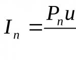
Wastewater dilution is a reduction in the concentration of pollutants in reservoirs due to mixing of wastewater with reservoir water. The intensity of dilution is characterized by the dilution factor
The amount of initial dilution depends on the design and location of the outlet, the hydraulic parameters of the watercourse and other factors.
Based on the type of reservoir, releases are classified into river, lake and sea. Based on their location, they are divided into coastal, channel and deep, and based on their design - into concentrated and scattering.
Channel outlets are a pipeline extended into the river bed and ending with one or more submerged ends. With one head, the release is called concentrated, and with several heads - scattering. Dissipated outlets are also made in the form of sections of pipes with holes or slots. The heads or holes are located at an equal distance from each other.
Deep outlets are similar to channel outlets. They are used when releasing wastewater into lakes, reservoirs and seas. They are distinguished by large depth of the heads.
1- retaining wall
2-sheet piling
3- securing the river bed


Channel outlets consist of a supply pipeline extended into the river bed and one (with a concentrated outlet) or several (with a scattering outlet) caps

Rice. 1. Scheme of channel dispersal release into the river
1 - gravity collector; 2 - coastal well; 3 - outlet supply pipeline; 4 - plant soil (turf); 5 - fastening the bank with reinforced concrete slabs; 6 - securing the bank with rock riprap; 7-heads; 8 - sand backfill
The heads of concentrated outlets are usually made in the form of rectangular, rhombic or teardrop-shaped concrete blocks and are located with their long axis along the flow.
The location of the release device should be determined taking into account factors that promote maximum mixing. On rivers, such places include areas with high flow rates and a winding channel, where, due to the transverse circulation of the flow, the diluting capacity of the river flow increases. The river bed at the release site must be stable. This is one of the most important conditions for the reliability of the release.
As noted above, the design of deep-water outlets is similar to the design of channel outlets. However, when designing them, the dynamic effect of the reservoir on the structure must be especially taken into account, and when installing outlets into the sea, the chemical effect of water must also be taken into account.
Pipelines for channel and deep-water outlets made of steel pipes with reinforced anti-corrosion insulation must be laid in a trench. If pipelines for deep-sea outlets are laid along the bottom surface, they should be secured with anchors or loading arrays.
Shore releases
Water is discharged into reservoirs through special structures - outlets. The design features of the outlets are dictated by the following conditions: ensuring the stability of the outlets themselves and ensuring maximum dilution of wastewater.
Based on their location, they are divided into coastal, channel and deep, and based on their design - into concentrated and scattering.
Onshore concentrated outlets are made in the form of pipes, the end of which is formed into the embankment, open channels, fast currents, multi-stage drops and heads of various designs. Shore releases provide virtually no initial dilution, and further dilution proceeds very slowly due to low movement speeds and shallow water depths in the reservoir near the shore. Shore outlets are used mainly for the discharge of atmospheric water into a reservoir.
The design of onshore outlets depends on the relative elevation (ratio of elevations) of the pipeline or channel and the water level in the reservoir, the amplitude of fluctuations in the water level in the reservoir, the discharged wastewater flow, the configuration of the coastal slope and a number of other factors.
It is recommended to design outlets that are not flooded, with free release of water into river beds or reservoirs, with the channel elevation not lower than the average low-water elevation. Flooded outlets may be designed in the following cases: if a non-flooded outlet can be damaged during freeze-up and ice drift; if the installation of an unflooded outlet is undesirable for architectural or sanitary reasons. Flooded outlets should be located below the lower edge of the ice during freeze-up.
Bank outlets consist of a retaining wall (head), fastening the river bank before and after the outlet, as well as in front of it and a connecting device.
The retaining wall is located at the end of the pipeline on the foundation, which is fenced off from the side of the reservoir with a sheet piling wall to prevent erosion. The retaining wall secures the end of the pipe, preventing its displacement and destruction. The role of a retaining wall within the city can be performed by an embankment. The fastening of the river bank is determined taking into account the geological conditions and hydrological features (flow speed, fluctuations in water levels, etc.) of the reservoir. It must ensure the stability of the river bed or the shore of a reservoir under any possible hydrological condition of the reservoir (flood, storm, etc.).
If the difference between the elevations of the pipeline and the water level in the reservoir is large, then it is necessary to install a connecting device that ensures the damping of the flow energy (flooding of the hydraulic jump, damping the flow speed) of the discharged wastewater. The connecting devices are made in the form of a multi-stage well or no-well drop, a high-flow with a water well at the base, etc.

4- retaining wall
5-sheet piling
6- securing the river bed
Dear Colleagues!!!
The page you requested is under reorganization.
We bring to your attention a new service for owners and managers of small and medium-sized enterprises and individual entrepreneurs
: "Increasing the profitability of small and medium-sized businesses by reducing unproductive costs and increasing labor productivity!!! Increasing the profitability of the business as a whole." .Health. Yours. Your loved ones. How are you feeling? Do you have chronic diseases? Chronic fatigue? Not very much, but do you get sick often (and the temperature often does not exceed 37 degrees)? Or you just want to lead an active lifestyle and extend your active longevity!!! In this case, we recommend that you familiarize yourself with the section of our website dedicated to restoring the body’s immune system!!! She needs your help!!! Help her!!! She will work wonders!!!
Steam meters, gas meters (TIRES LLC). .
Equipment for electrical network protection systems, automation and control from the company NPP Novatek-Electro.
Total informationK category: Cleaning of drains
Treated wastewater during artificial treatment is discharged through a canal to the place where it is discharged into the reservoir. The diversion channel usually ends with a shore well, from which treated wastewater is discharged into the reservoir through an outlet. The more favorable the conditions for mixing the discharged wastewater with the waters of the reservoir, the better the self-purifying ability of the reservoir is used, the more contaminated the wastewater can be discharged into it.
Wastewater discharges are classified by type of reservoir (river, lake and sea), by location (shore, channel and deep) and by design (concentrated and diffuse).
Onshore concentrated outlets are designed in the form of open channels, fast currents, cantilever faults, and caps. In this case, a very slight dilution of the discharged wastewater with the water of the reservoir occurs, so the use of the self-purifying ability of the reservoirs is very low. Such outlets are used for the discharge of rainwater or lightly polluted wastewater. More often, channel dispersing outlets are installed to ensure the best mixing of wastewater with river water. Deep outlets are used when discharging wastewater into lakes, reservoirs, and seas.
The outlet is a perforated steel pipe with a metal casing with slots. The cage is filled with gravel or crushed stone. The area of the slotted holes in the lattice bottom of the cage is 40-50% of its area. The outlet of water in the form of vertical jets ensures effective mixing with the water of the reservoir.
Part 2
Treated wastewater is discharged through a canal to the point where it is discharged into the reservoir. The drainage channel usually ends with a shore well, from which treated wastewater is discharged into the reservoir through the so-called outlet. The design of the outlet is essential for deciding the required degree of wastewater treatment. The more favorable the conditions for mixing the discharged water with the water of the reservoir, the more the self-purifying ability of the reservoir is used, the lower the required degree of wastewater treatment. The following discharge designs are distinguished: concentrated, through which water is discharged into the reservoir through only one hole; dispersive, in which water is discharged through a series of holes. In practical conditions, both outlets are used, but the dispersing outlet is more widespread, since it provides better mixing of wastewater with reservoir water.
Rice. 1. Dissipative outlet with tees and elbows

Rice. 2. General view of the dissipative release
The release should be brought to the middle of the river. Where the outlet is installed, the river bottom must be protected from erosion and siltation.
The choice of a place for discharging treated wastewater must be agreed with the sanitary inspection authorities, shipping departments and other organizations that are interested in maintaining the conditions of normal operation of the reservoir.
Currently, in most cases, the following designs of dispersive sewer outlets are used: outlets with tees and elbows (Fig. 1) and with tees (Fig. 2).
In Fig. Figure 2 shows a general view of the dissipative outlet of the Giprospetsneft structure with water distribution through tees.
Recently, Eng. A. X. Maksimov. (Leningrad) a simplified design of the dissipative outlet was proposed, providing good operating conditions. Water is released through holes in the pipe located at a certain distance from each other.
Eng. A. Kh. Maksimov also developed a theory of hydraulic calculation of such a release, based on the fact that with the gradual distribution of water through the holes, the so-called movement of a fluid with variable mass takes place.

LABOR RELATIONS their features. Labor relations are relations based on an agreement between the employee and...

Slides: 11 Words: 183 Sounds: 0 Effects: 0 Clear water. Determination of water purity. Reservoirs. Spring. Oceans. Ocean -...
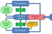
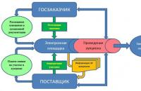
What is a tender - the essence of the process. Classification into 3 types + 5 areas for tenders. How to take part in...

A profession is a limited (due to the division of labor) area of application of a person’s physical and/or spiritual forces...

The life of a modern person cannot be imagined without machines and other mechanized devices. It's quite logical that...

A cover letter for a resume is a document in which you can present yourself in a more free manner at your best...

1 of 39 Presentation on the topic: Rules of safe behavior Slide No. 1 Slide description: Slide No. 2...

The law prohibits working without vacation, receiving a cash equivalent instead of the allotted vacation once a year. But this...

Joshua Milton - "General Butt Naked": Joshua Milton Blahy, better known as "General Butt Naked"...
In conditions of horizontal differentiation, the buyer's choice is determined by commitment to a particular brand,...

Vertical product differentiation involves the distribution of products in an industry market in accordance with...

A citizen of the Russian Federation (each individual) is a consumer of state resources: water (for hot and cold),...
In many areas of life there are such concepts as centralization and decentralization. These concepts are included...

Get acquainted with draft orders of management relating to its activities. 3.8. Sign and endorse...

Slides: 11 Words: 183 Sounds: 0 Effects: 0 Clear water. Determination of water purity. Reservoirs. Spring. Oceans....
What is a tender - the essence of the process. Classification into 3 types + 5 areas for tenders. How to take...