02.11.2020
Recommendations for the device and safe operation of technological pipelines. Industrial safety requirements for the operation of process pipelines chapter general provisions
Pipelines are designed to transport compressed air, water, steam, various gases and liquids. To quickly determine the content of pipelines, and, consequently, compliance by workers with the relevant safety requirements when approaching them, ten groups of substances and the corresponding distinctive color of the pipelines by which they are transported have been established: the first is water (green), the second is steam (red), the third is air. (blue), fourth and fifth - flammable and non-flammable gases, including liquefied (yellow), sixth - acids (orange), seventh - alkalis (purple), eighth and ninth - flammable and non-flammable liquids (brown), zero - other substances ( The distinctive coloring of pipelines is carried out along their entire length or in individual sections, depending on the location, illumination, size, etc. In order to highlight the type of danger, color signal rings are applied to the pipelines: red - for flammable, explosive -and flammable substances; yellow - for harmful and hazardous substances (poisonous, toxic, radioactive); green - for safe and neutral substances. Sometimes, to specify the type of hazard, in addition to the color signal rings, warning signs, marking plates and inscriptions on pipelines in the most dangerous places of communications are used. The laying of pipelines on the territory of the enterprise can be underground (in channels and channelless), above-ground (on supports) and above-ground (on overpasses, columns, walls of buildings, etc.). If possible, it is advisable to carry out above-ground and above-ground laying of pipelines, since then it is easy to inspect and check their condition. In addition, the service life of such pipelines is two to three times longer than in underground ones. The pipelines are made of seamless pipes with welded joints. To facilitate installation and repair, flange connections are installed on the pipeline in convenient and accessible places. Pipelines are laid with a certain slope (1: 500) in the direction of gas movement, and in low places separators with drain valves are installed to remove condensate and water. In order to prevent thermal stresses that can cause breaks during cooling of pipes or bends when they are heated, on pipelines provide compensation elements: expansion loops, lyre pipes, stuffing box expansion joints, etc. The most common are U-shaped expansion loops, which allow evenly distribute thermal deformations along the pipeline. To ensure safety, the pipeline must be installed in good working order and properly adjusted pressure reducing, check, shutoff and safety valves. Reducing valves (pressure regulators) maintain the set pressure values in the system regardless of changes in the gas or liquid flow rate by consumers. Check valves allow gas or liquid to pass through the pipeline in only one direction, therefore, prevent their reverse stroke in the event of an emergency (for example, a fire in a combustible gas pipeline). When the permissible pressure is exceeded, the check valves automatically open, and part of the gas or liquid is discharged into the atmosphere or the utilization channel. If poisonous, toxic, explosive or flammable gases or liquids are transported through the pipeline, the safety valves must be of a closed type (when opened, gas or liquid is released into a closed system). The pipelines are periodically subject to external inspections and hydraulic tests. During external examinations, the condition of welded and flanged joints, glands is determined, slopes, deflections, strength of bearing supports and structures are checked. During hydraulic tests, the tightness and strength of the pipeline are checked. If during the hydraulic test the pressure in the pipeline did not drop, and no cracks, ruptures, or leaks were found on the welded seams, flange joints, housings of safety devices, then the test result is considered satisfactory. installation of compensating elements, necessary safety devices and fittings, control of their technical condition and timely repair. Natural gas is widely used at many enterprises and in everyday life, most often as a fuel. Considering that natural gas belongs to explosive substances, the gas pipeline, together with installations that regulate the gas supply and operate on it as an object of increased danger, therefore requires special care during operation. As a rule, gas leakage is the cause of accidents, explosions, fires during the operation of gas facilities and gas pipelines. Since natural gas is odorless, an odorant, a substance with a strong odor (for example, ethyl mercaptan), is added to it to quickly detect its leakage. To prevent the occurrence of hazardous induced currents that can cause explosions and fires, gas pipelines must be grounded and conductive jumpers must be installed on all flange connections.
GOSGORTEKHNADZOR OF RUSSIA
APPROVED BY
Resolution No. 11
Gosgortekhnadzor of Russia
from 02.03.95
DEVICE RULES
AND SAFE OPERATION
TECHNOLOGICAL PIPELINES
Mandatory for all businesses and organizations
regardless of departmental affiliation and
organizational and legal forms
PB 03-108-96
Editorial Commission:
E. A. Malov (chairman), A. A. Shatalov (deputy chairman), L. N. Ganshina, B. M. Gusev, S. I. Zusmanovskaya, G. V. Kiryukhin, V. N. Konovalov, N. V. Martynov, Yu. S. Medvedev, E. Ya. Neiman, N. A. Potapov, V. B. Serebryany, R. A. Standrik, S. G. Starodub, G. M. Khazhinsky, N. V. Khimchenko, M.P. Elyash.
"Rules for the design and safe operation of technological pipelines" were developed by the Gosgortekhnadzor of Russia, the Nizhne-Volzhsky District of the Gosgortekhnadzor of Russia, research and design institutes: VNIKTIneftehimoborudovaniya, NIICHIMMASH, Giprohimmontazh, IrkutskNIIhimmash, GIAP, VNIIneftemash, VNIPIneft, YuzhNIIgiprogaz, JSC "Sintezproekt" VNIImontazhspetsstroy taking into account comments of the Bashkir County Gosgortechnadzor Russia, JSC "Angarsk Oil Company", JSC "Salavatnefteorgsintez", JSC "Kuibyshevazot" NIIPThimnefteapparatury, OJSC "Nizhnekamskneftekhim" and other interested organizations and enterprises.
These Rules establish general provisions and the main technical requirements for process pipelines: conditions for the selection and use of pipes, pipeline parts, fittings and basic materials for their manufacture, as well as requirements for welding and heat treatment, placement of pipelines, conditions of normal operation and repair, the observance of which is mandatory for all industries, having production under the control of Gosgortekhnadzor of Russia.
With the entry into force of these Rules, the Rules for the Construction and Safe Operation of Pipelines for Flammable, Toxic and Liquefied Gases (PUG-69), approved by the USSR Gosgortekhnadzor in 1969, become invalid.
All current industry normative and technical documents and instructions regarding the design, installation, operation and repair of steel in-house and workshop process pipelines must be brought in accordance with these Rules.
The necessity and timing of bringing the existing pipelines in accordance with these Rules are determined by the administration of the enterprise and agreed with the regional bodies of the Gosgortechnadzor of Russia.
1. GENERAL PROVISIONS
1.1. Application area
1.1.1. The rules for the design and safe operation of technological pipelines * apply to the design, construction, manufacture, installation, operation and repair of stationary steel technological pipelines intended for the transportation of gaseous, vaporous and liquid media in the range of residual pressure (vacuum) 0.001 MPa (0.01 kgf / cm 2) up to a nominal pressure of 320 MPa (3200 kgf / cm 2) and operating temperatures from minus 196 to plus 700 ° C for chemical, petrochemical, oil refining, gas processing, chemical-pharmaceutical, pulp and paper, microbiological, coke-chemical, petro- and gas production enterprises.
* Rules for the construction and safe operation of technological pipelines hereinafter referred to as the Rules.
Notes. 1. Process pipelines include pipelines within industrial enterprises, through which raw materials, semi-finished and finished products, steam, water, fuel, reagents and other substances that ensure the conduct of the technological process and the operation of equipment are transported, as well as interfactory pipelines that are on the balance sheet of the enterprise ...
2. The terms "pressure", "conditional pressure", unless otherwise specified, should be understood as overpressure.
1.1.2. Along with these Rules, in the design, construction and operation of technological pipelines, one should also be guided by the relevant sections of the Construction Norms and Rules (SNiP), the corresponding rules of the Gosgortekhnadzor of Russia and other mandatory rules and regulations.
In this case, one should take into account the requirements of fire and explosion safety, industrial sanitation and labor protection, set out in the relevant regulatory and technical documents (NTD), approved in the prescribed manner.
1.1.3. When designing and operating pipelines for liquid and gaseous chlorine, along with these Rules, one should be guided by the Safety Rules for the production, storage, transportation and use of chlorine (PBH-93).
1.1.4. When designing and operating air and inert gas pipelines, along with these Rules, one should be guided by the requirements of the Rules for the Construction and Safe Operation of Stationary compressor units, air and gas pipelines.
1.1.5. When designing and operating pipelines transporting gas containing hydrogen sulfide, along with these Rules, one should be guided by industry-specific scientific and technical documentation agreed with the Gosgortechnadzor of Russia, and the recommendations of specialized research organizations.
1.1.6. These Rules do not apply to pipelines:
trunk pipelines (gas pipelines, oil pipelines and product pipelines);
acetylene and oxygen;
power plants, boiler houses, mines;
heating networks, water supply and sewerage lines;
lined with non-metallic materials;
gases containing explosive dust and fiber;
temporary, constructed for the period of construction, installation or reconstruction of an enterprise or workshop, with a service life of no more than 1 year;
special purposes (nuclear plants, mobile units, lubrication systems that are an integral part of equipment, etc.);
steam and hot water of category I with a diameter of 51 mm and more, as well as all other categories with a diameter of 76 mm and more, which are subject to the requirements of the Rules for the construction and safe operation of steam and hot water pipelines;
fuel gas, which are subject to the Safety Rules in the gas industry, when using gas from main and city gas pipelines or liquefied gases as fuel.
1.1.7. Depending on the working pressure, the process pipelines to which these Rules apply are subdivided into low-pressure process pipelines with a nominal pressure of up to 10 MPa (100 kgf / cm 2) inclusive and high-pressure process pipelines with a nominal pressure of over 10 MPa (100 kgf / cm 2) up to 320 MPa (3200 kgf / cm 2).
1.1.8. Development of industry-specific normative documents regulating the conditions and requirements of a particular industry, within the main provisions and requirements of these Rules.
1.2. Basic Provisions
1.2.1. These Rules establish the basic technical requirements for the design, construction, manufacture, installation, operation and repair of technological steel pipelines, as well as the conditions for the selection and use of pipes, pipeline parts, fittings and basic materials. Compliance with these Rules is mandatory for all enterprises and organizations engaged in the design, manufacture, installation and operation of technological pipelines, regardless of departmental subordination and organizational and legal forms.
1.2.2. For pipes, fittings and pipe fittings conditional ( R y) and the corresponding test ( R pr), as well as workers ( R slave) pressures are determined in accordance with GOST 356. At a negative operating temperature of the medium, the nominal pressure is determined at a temperature of plus 20 ° C.
1.2.3. The wall thickness of pipes and pipeline parts should be determined by a strength calculation depending on the operating (design) parameters, corrosion and erosion properties of the medium in accordance with regulatory and technical documents in relation to the current range of pipes. When choosing the wall thickness of pipes and pipeline parts, the peculiarities of their manufacturing technology (bending, assembly, welding) should be taken into account.
The maximum working (design) pressure in the pipeline is taken as:
permitted pressure for the apparatus to which the pipeline is connected;
for pressure pipelines (after pumps, compressors, gas blowers) - the maximum pressure developed by the centrifugal machine with a closed valve on the pressure side; and for piston machines - the response pressure of the safety valve installed on the pressure source;
for pipelines with safety valves installed on them - the pressure of the safety valve.
Pipelines that are tested for strength and tightness together with the apparatus must be rated for strength taking into account the test pressure of the apparatus.
1.2.4. When calculating the wall thickness of pipelines, the increase in compensation for corrosive wear to the calculated wall thickness must be selected based on the condition of ensuring the required pipeline service life in accordance with the current standards for the use of materials in technological processes and the corrosion rate.
Depending on the corrosion rate of carbon steels, the media are divided into:
non-aggressive and low-aggressive - with a corrosion rate of up to 0.1 mm / year;
moderately aggressive - with a corrosion rate of 0.1-0.5 mm / year;
highly aggressive - with a corrosion rate of over 0.5 mm / year.
1.2.5. When choosing materials and products for pipelines, one should be guided by the requirements of these Rules, as well as the instructions of industry and interbranch scientific and technical documentation that establish their assortment, nomenclature, types, main parameters, conditions of use, etc. It should be borne in mind:
working pressure and working temperature of the transported medium;
properties of the transported and the environment(aggressiveness, explosion and fire hazard, harmfulness, etc.);
properties of materials and products (strength, cold resistance, corrosion resistance, weldability, etc.);
ambient air temperature for pipelines located outdoors or in unheated rooms. For the design air temperature when choosing materials and products for pipelines, the average temperature of the coldest five-day period should be taken according to SNiP 2.01.01-82.
1.2.6. For the choice of the pipeline scheme, the correctness of its design, strength calculation and choice of material, for the accepted service life, quality of manufacture, installation and repair, as well as for the compliance of the pipeline with the requirements of rules, standards and other NTDs, are the responsibility of organizations or enterprises that performed the relevant work.
1.2.7. All project changes arising in the process of manufacturing, installation and repair of the pipeline, including the replacement of materials, parts and changes in the category of pipelines must be carried out by an organization licensed by the Gosgortekhnadzor of Russia for the right to design pipelines.
1.2.8. The organization operating the pipeline (the owner of the pipeline) bears full responsibility for the correct and safe operation of the pipeline, control over its operation, for the timeliness and quality of the audit and repair in accordance with these Rules, as well as for coordination with the author of the project of all changes made into the object and project documentation.
1.2.9. For pipelines and fittings in contact with explosive and hazardous environments, design organization the estimated service life is established, which should be reflected in the project documentation and entered in the pipeline passport.
Operation of pipelines that have fulfilled their estimated service life is allowed upon receipt of a technical opinion on the possibility of its further work and permission in the manner prescribed by regulatory documents.
1.2.10. Organizations engaged in the design, manufacture, installation, repair, operation and technical diagnostics of pipelines must have a license from the Gosgortekhnadzor of Russia for the work performed.
2. TECHNOLOGICAL PIPELINES WITH NOMINAL PRESSURE UP TO 10 MPa (100 kgf / cm 2)
2.1. Classification of pipelines
2.1.1. All pipelines with pressure up to 10 MPa (100 kgf / cm 2) (inclusive), depending on the hazard class of the transported substance (explosion, fire hazard and hazard) are divided into groups (A, B, C) and depending on the operating parameters of the environment ( pressure and temperature) - into five categories (I, II, III,
IV, V).
The classification of pipelines is given in table. ...
Table 2.1
Classification of pipelines R at
£
10 MPa (100 kgf / cm 2)
|
| Transported substances
|
|
|
|
| III
|
|
|
| R
slave, MPa (kgf / cm 2)
| t
slave, ° С
| R
slave, MPa (kgf / cm 2)
| t
slave, ° С
| R
slave, MPa (kgf / cm 2)
| t
slave, ° С
| R
slave, MPa (kgf / cm 2)
| t
slave, ° С
| R
slave, MPa (kgf / cm 2)
| t
slave, ° С
|
|
|
|
|
|
|
|
|
|
|
|
|
|
|
| Substances with toxic effects
|
|
|
|
|
|
|
|
|
|
|
| a) extremely and highly hazardous substances of classes 1, 2 (GOST 12.1.007 )
| Whatever
| Whatever
|
|
|
|
|
|
|
|
|
| b) moderately hazardous substances of class 3 (GOST 12.1.007 )
| Over 2.5 (25)
| Above +300 and below -40
|
| -40 to +300
|
|
|
|
|
|
|
| Vacuum below 0.08 (0.8) (abs)
| Whatever
|
|
|
|
|
|
|
|
|
|
| Explosive and flammable substancesGOST 12.1.044
|
|
|
|
|
|
|
|
|
|
|
| a) combustible gases (GG), including liquefied gases (LPG)
| Over 2.5 (25)
| Above +300 and below -40
| Vacuum from 0.08 (0.8) (abs) to 2.5 (25)
| -40 to +300
|
|
|
|
|
|
|
| Vacuum below 0.08 (0.8) (abs)
| Whatever
|
|
|
|
|
|
|
|
|
| b) flammable liquids (flammable liquids)
| Over 2.5 (25)
| Above +300 and below -40
| Over 1.6 (16) to 2.5 (25)
| +120 to +300
| Up to 1.6 (16)
| -40 to +120
|
|
|
|
|
| Vacuum below 0.08 (0.8) (abs)
| Whatever
| Vacuum above 0.08 (0.8) (abs)
| -40 to +300
|
|
|
|
|
|
|
| c) flammable liquids (GZh)
| Over 6.3 (63)
| Above +350 and below -40
| Over 2.5 (25) to 6.3 (63)
| Over +250 to +350
| Over 1.6 (16) to 2.5 (25)
| Over +120 to +250
| Up to 1.6 (16)
| -40 to +120
|
|
|
| Vacuum below 0.003 (0.03) (abs)
| Also
| Vacuum below 0.08 (0.8) (abs)
| Also
| Vacuum up to 0.08 (0.8) (abs) | Over +350 to +450
| Over 2.5 (25) to 6.3 (63)
| From +250 to +350
| Over 1.6 (16) to 2.5 (25)
| Over +120 to +250
| Up to 1.6 (16)
| -40 to +120
|
Notes. 1. The designation of the group of a certain transported medium includes the designation of the general group of the medium (A, B, C) and the designation of the subgroup (a, b, c), reflecting the hazard class of the transported substance.
2. The designation of the pipeline group in general corresponds to the designation of the group of the transported medium. The designation "pipeline of group A (b)" denotes the pipeline through which the medium of group A (b) is transported.
3. A group of a pipeline transporting a medium, consisting of various components, is installed according to a component that requires the pipeline to be assigned to a more responsible group. Moreover, if the concentration of one of the components is lethal when the mixture contains hazardous substances of 1, 2 and 3 hazard classes, the group of the mixture is determined by this substance.
If the most dangerous component in terms of physical and chemical properties is included in the mixture in an insignificant amount, the issue of attributing the pipeline to a less responsible group or category is decided by the design organization (the author of the project).
4. The hazard class of harmful substances should be determined in accordance with GOST 12.1.005 and GOST 12.1.007, the values of the indicators of fire and explosion hazard of substances - according to the relevant NTD or the methods set forth in GOST 12.1.044.
6. For vacuum lines, not the nominal pressure, but the absolute working pressure should be taken into account.
7. Pipelines transporting substances with an operating temperature equal to or higher than their autoignition temperature or an operating temperature below minus 40 ° C, as well as incompatible with water or air oxygen under normal conditions, should be classified as category I.
2.1.2. Categories of pipelines determine the totality of technical requirements for the design, installation and scope of inspection of pipelines in accordance with these Rules.
2.1.3. The hazard class of technological environments is determined by the project developer based on the hazard classes of substances contained in the technological environment and their ratios in accordance with GOST 12.1.007.
2.1.5. By the decision of the developer, it is allowed, depending on the operating conditions, to accept a more responsible (than determined by the operating parameters of the environment) category of pipelines.
2.2. Requirements for materials used for pipelines
2.2.1. Pipes, shaped fittings, flanges, gaskets and fasteners used for steel process pipelines, in terms of quality, technical characteristics and materials, must meet the requirements of these Rules and the relevant regulatory and technical documents.
Quality and technical specifications materials and finished products used for the manufacture of pipelines must be confirmed by manufacturers with appropriate passports or certificates. Materials and products that do not have passports or certificates are allowed to be used only for pipelines of II and lower categories and only after they have been checked and tested in accordance with standards, specifications and these Rules.
The material of the piping parts, as a rule, must match the material of the pipes to be connected. When using and welding dissimilar steels, the instructions of the relevant regulatory and technical documents should be followed.
It is allowed, upon the conclusion of specialized research organizations, to use pipes and pipeline parts made of materials not specified in these Rules.
2.2.2. Pipes and fittings of pipelines must be made of steel with technological weldability, with a ratio of yield strength to tensile strength of no more than 0.75, relative elongation of the metal at break at fivefold samples of at least 16% and impact strength of at leastKCU =
30 J / cm 2 (3.0 kgf ·
m / cm 2) at the minimum allowable temperature of the pipeline element wall during operation.
2.2.3. The use of imported materials and products is allowed if the characteristics of these materials meet the requirements of domestic standards and are confirmed by the conclusion of a specialized research organization.
Approved
by order of the Minister for Emergency Situations of the Republic of Kazakhstan
Industrial safety requirements for
operation of technological pipelines
Chapter 1. General Provisions
1. These Requirements apply to designed, newly manufactured and modernized steel process pipelines intended for transportation of gaseous, vaporous and liquid media in the range from residual pressure (vacuum) 0.001 MPa (0.01 kgf / cm) to nominal pressure 320 MPa (3200 kgf / cm) and operating temperatures from -196 ° C to 700 ° C and operated at hazardous production facilities.
2. The wall thickness of pipes and pipeline parts is determined by the strength calculation depending on the design parameters, corrosion and erosion properties of the medium in accordance with the regulatory and technical documents in relation to the current range of pipes. When choosing the wall thickness of pipes and pipeline parts, the peculiarities of their manufacturing technology (bending, assembly, welding) are taken into account.
The design pressure in the pipeline is taken as follows:
1) design pressure for the apparatus with which the pipeline is connected;
2) for pressure pipelines (after pumps, compressors, gas blowers) - the maximum pressure developed by the centrifugal machine with a closed valve on the discharge side; and for piston machines - the response pressure of the safety valve installed on the pressure source;
3) for pipelines with installed safety valves - setting pressure of the safety valve.
The pipelines, which are tested for strength and tightness together with the apparatus, are designed for strength taking into account the test pressure of the apparatus. 3. When calculating the wall thickness of pipelines, the allowance for compensating for corrosive wear to the calculated wall thickness should be selected based on the condition of ensuring the required estimated pipeline service life and corrosion rate.
Depending on the corrosion rate of steels, the media are divided into:
1) non-aggressive and low-aggressive - with a corrosion rate of up to 0.1 mm / year (resistant steel);
2) moderately aggressive - with a corrosion rate of 0.1-0.5 mm / year;
3) highly aggressive - with a corrosion rate of over 0.5 mm / year.
At a corrosion rate of 0.1-0.5 mm / year and over 0.5 mm / year, steel is considered to be low-resistant.
4. When choosing materials and products for pipelines, take into account:
1) design pressure and design temperature of the transported medium;
2) the properties of the transported medium (aggressiveness, explosion and fire hazard, harmfulness, etc.);
3) properties of materials and products (strength, cold resistance, corrosion resistance, weldability, etc.);
4) negative ambient temperature for pipelines located outdoors or in unheated rooms. For the calculated, negative air temperature when choosing materials and products for pipelines, one should take:
the average temperature of the coldest five-day period of the region with a security of 0.92, if the working temperature of the pipeline wall, under pressure or vacuum, is positive;
the absolute minimum temperature of a given area, if the working temperature of the pipeline wall, under pressure or vacuum, becomes negative from the influence of ambient air.
5. For pipelines and valves, the design organization sets the service life in the design documentation.
Chapter 2. Process pipelines with nominal pressure
up to 10 MPa (100 kgf / cm)
Section 1. Classification of pipelines
6. Pipelines with a pressure of up to 10 MPa (100 kgf / cm) inclusively, depending on the hazard class of the transported substance (explosion, fire hazard and harmfulness) are divided into groups A, B, C and depending on the operating parameters of the environment (pressure and temperature) - into five categories (I, II, III, IV, V).
The classification of pipelines is given in Appendix 1 of these Requirements.
8. The hazard class of technological environments is determined by the project developer on the basis of the hazard classes of substances contained in the technological environment and their ratios.
10. It is allowed, depending on the operating conditions, to accept a higher (than determined by the operating parameters of the environment) category of pipelines.
The designation of the group of a certain transported medium includes the designation of the medium group (A, B, C) and the designation of the subgroup (a, b, c), reflecting the hazard class of the substance.
The designation of the pipeline group in general corresponds to the designation of the group of the transported medium. The designation "pipeline of group A (b)" denotes the pipeline through which the medium of group A (b) is transported.
A group of pipeline transporting a medium, consisting of various components, is installed according to the component that requires the pipeline to be assigned to a more responsible group. If the mixture contains hazardous substances of 1, 2 and 3 hazard classes and if the concentration of one of them is the most dangerous, the group of the mixture is determined by this substance.
If the most dangerous in terms of physical and chemical properties component is included in the mixture in an insignificant amount, the issue of attributing the pipeline to a less responsible group or category is decided by the design organization.
For vacuum pipelines, not the nominal pressure is taken into account, but the absolute working pressure.
Pipelines transporting substances with an operating temperature equal to or higher than their autoignition temperature or an operating temperature below -40 ° C, as well as incompatible with water or air oxygen under normal conditions, are classified as category I.
Paragraph 2. Requirements for materials used for pipelines
11. Pipes, fittings, flanges, gaskets and fasteners used for pipelines, in terms of quality, technical characteristics and materials, comply with the relevant regulatory and technical documentation.
The quality and technical characteristics of materials and finished products used for the manufacture of pipelines are confirmed by the manufacturer's certificates. Materials and products that do not have certificates are allowed to be used only for pipelines of II and lower categories and after their inspection and testing, in accordance with the normative and technical documentation.
The material of the piping parts matches the material of the pipes to be connected When using dissimilar pipes and welding them, they are guided by the instructions of the relevant regulatory and technical documents.
12. Pipes and fittings of pipelines are made of steel with technological weldability, with a ratio of yield strength to tensile strength of no more than 0.75, relative elongation of the metal at break at fivefold samples of at least 16% and impact strength of at least 30 J / cm ( 3.0 kgf m / cm) at the minimum design temperature of the pipeline element wall.
13. Pipes, depending on the parameters of the transported medium, are selected in accordance with the normative and technical documentation.
14. Seamless pipes Shaped parts made from ingots for these pipes may be used for pipelines of groups A and B of the first and second categories, provided that they are inspected by ultrasonic flaw detection (hereinafter - UZD) in the amount of 100% over the entire surface.
15. For pipelines transporting liquefied hydrocarbon gases (hereinafter referred to as LPG), as well as substances belonging to group A (a), seamless hot and cold-deformed pipes should be used. In accordance with the instructions of the normative and technical documentation, the use of electro welded pipes nominal diameter of more than 400 mm for pipelines of transporting substances belonging to group A (a) and liquefied hydrocarbon gases at a metal corrosion rate of up to 0.1 mm / year, with a working pressure of up to 2.5 MPa (25 kgf / cm) and a temperature up to 200 ° C, heat-treated, one hundred percent inspection of welded joints (by ultrasonic inspection or transillumination) with positive results of mechanical tests of samples from welded joints in full, including for impact toughness.
It is allowed to use shells made of sheet steel as pipes, in accordance with the requirements of the device and safe operation of vessels operating under pressure, for a nominal pressure of up to 2.5 MPa (25 kgf / cm).
16. For pipelines, pipes with normalized chemical composition and mechanical properties of metal (group B) are used.
17. Pipes have been tested by the manufacturer with a test hydraulic pressure specified in the normative and technical documentation for pipes, or have an indication in the certificate of the guaranteed test pressure value.
It is allowed not to hydrotest seamless pipes if they were subjected to non-destructive testing over the entire surface.
18. Electric-welded pipes with a spiral seam are allowed to be used only for straight sections of pipelines.
19. Electric-welded pipes used for the transportation of substances of groups A (b), B (a), B (b) (Appendix 1), with the exception of liquefied gases with a pressure of more than 1.6 MPa (16 kgf / cm) and groups B (c ) and B pressure over 2.5 MPa (25 kgf / cm), with an operating temperature over 300 ° C in the heat-treated state, and their welded seams were subjected to 100% non-destructive testing (by ultrasonic inspection or radiography) and bending or impact toughness tests.
It is allowed to use non-heat-treated pipes with a ratio of the outer diameter of the pipe to the wall thickness equal to or more than 50 for transporting media that do not cause corrosion cracking of the metal.
20. Electric-welded pipes in contact with the medium causing corrosion cracking of the metal, regardless of pressure and wall thickness in the heat-treated state, and their welded seams are equal in strength to the base metal and are subjected to 100% non-destructive testing (ultrasonic inspection or radiography).
21. Pipes made of semi-calm carbon steel are allowed to be used for media of group B with a wall thickness of no more than 12 mm in areas with a design temperature of the outside air not lower than -30 ° C while ensuring the temperature of the pipeline wall during operation is not lower than -20 ° C.
Pipes made of boiling carbon steel are allowed to be used for media of group B with a wall thickness of no more than 8 mm and a pressure of no more than 1.6 MPa (16 kgf / cm) in areas with a design air temperature of at least -10 ° C.
22. The design of flanges and materials for them should be selected taking into account the parameters of the working environments according to the normative and technical documentation.
23. Flat welded flanges are used for pipelines operating at a nominal pressure of no more than 2.5 MPa (25 kgf / cm) and an ambient temperature of no higher than 300 ° C. For pipelines of groups A and B with a nominal pressure of up to 1 MPa (10 kgf / cm), flanges are used, provided for a nominal pressure of 1.6 MPa (16 kgf / cm).
24. For pipelines operating at a nominal pressure over 2.5 MPa (25 kgf / cm), regardless of temperature, as well as for pipelines with an operating temperature above 300 ° C, regardless of pressure, butt-welded flanges are used.
25. Butt weld flanges are made from forgings or banding blanks.
It is allowed to manufacture butt-welded flanges by rolling blanks along the plane of the sheet for pipelines operating at a nominal pressure of not more than 2.5 MPa (25 kgf / cm), or bending forged strips for pipelines operating at a nominal pressure of not more than 6.3 MPa (63 kgf / cm), subject to one hundred percent inspection of welded seams by a radiographic or ultrasonic method.
26. When choosing the type of flange sealing surface, be guided by Appendix 2 of these Requirements.
27. For pipelines transporting substances of groups A and B of technological objects of the 1st category of explosion hazard, it is not allowed to use flange connections with a smooth sealing surface, except for the cases of using spiral wound gaskets with a restraining ring.
28. Fasteners for flange connections and materials for them should be selected depending on the working conditions and steel grades of the flanges.
To connect flanges at temperatures above 300 ° C and below -40 ° C, regardless of pressure, use studs.
29. When making studs, bolts and nuts, the hardness of the studs or bolts is higher than the hardness of the nuts by at least 10 - 15 HB.
30. It is not allowed to make fasteners from boiling, semi-calm, Bessemer and free-cutting steels.
31. Material of workpieces or finished fasteners made of high-quality carbon, heat-resistant and heat-resistant alloy steels are heat-treated.
For fasteners used at pressures up to 1.6 MPa (16 kgf / cm) and operating temperatures up to 200 ° C, fasteners made of carbon steel with threads up to 48 mm in diameter are allowed not to heat treatment.
32. In the case of using fasteners made of steels of austenitic class at an operating temperature of the medium above 500 ° C, it is not allowed to manufacture a thread by the knurling method.
33. Materials of fasteners should be selected with a coefficient of linear expansion close in value to the coefficient of linear expansion of the flange material with a difference in the values of the coefficients of linear expansion of materials not exceeding 10%.
It is allowed to use materials of fasteners and flanges with coefficients of linear expansion, the values of which differ by more than 10%, in cases justified by strength calculations or experimental studies, for flanged joints at an operating temperature of not more than 100 ° C.
34. Gaskets and gasket materials for sealing flange connections are selected depending on the transported medium and its operating parameters in accordance with the project, regulatory and technical documentation.
35. Shaped parts of pipelines, depending on the parameters of the transported medium and operating conditions, to choose according to the normative and technical documentation.
36. Shaped parts of pipelines shall be made of steel seamless and longitudinal welded pipes or sheet metal, the metal of which meets the requirements of the project, regulatory and technical documentation, conditions of weldability with the material of the pipes to be connected.
37. Details of pipelines for environments causing corrosion cracking of metal, regardless of design, steel grade and manufacturing technology, are subject to heat treatment.
Local heat treatment of welded joints of sectional bends and welded tees from pipes is allowed if heat-treated pipes are used for their manufacture.
38. When choosing welded parts of pipelines, depending on the aggressiveness of the environment, temperature and pressure, be guided by the normative and technical documentation.
39. Welding of fittings and quality control of welded joints shall be carried out in accordance with the requirements of normative-technical and project documentation.
40. A branch from the pipeline is performed in one of the ways set out in Appendix 3 of these Requirements. Reinforcement of tee connections with stiffeners is not allowed.
41. Connection of branches according to method "a" (Appendix 3) is used in cases where the weakening of the main pipeline is compensated by the existing safety margins of the connection.
42. When choosing a method for connecting branches to the main pipeline, give preference to methods "b", "c", "e" (Appendix 3).
43. The cover on the branch pipeline (connection according to the method "e" in Appendix 3) is installed when the ratio of the diameters of the branch and main pipelines is not less than 0.5.
44. Welded tees are used at a pressure of P y - up to 10 MPa (100 kgf / cm).
45. Bends welded with a nominal bore D y = 150 ÷ 400 mm should be used for process pipelines at a pressure P at no more than 6.3 MPa (63 kgf / cm).
Welded bends with nominal bore D y = 500 ÷ 1400 mm are allowed to be used for process pipelines at a pressure P y not exceeding 2.5 MPa (25 kgf / cm 2).
46. Welded concentric and eccentric transitions with nominal bore D y = 250 ÷ 400 mm are allowed to be used for process pipelines at pressure Р у up to 4 MPa (40 kgf / cm), and with D у 500 ÷ 1400 mm - with Р у up to 2 , 5 MPa (25 kgf / cm).
The limits of application of steel transitions, depending on the temperature and aggressiveness of the medium, correspond to the limits of use of the connected pipes for similar steel grades.
Weld seams of transitions are subject to one hundred percent inspection by ultrasonic or radiographic methods.
47. It is allowed to use petal transitions for process pipelines with nominal pressure P y not more than 1.6 MPa (16 kgf / cm) and nominal diameter D y = 100 ÷ 500 mm.
It is not allowed to install petal crossings on pipelines intended for the transportation of liquefied gases and substances of group A (a) (Appendix 1).
48. Flap transitions are welded with subsequent 100% inspection of welded seams by ultrasonic or radiographic methods.
After manufacturing, the petal transitions are subject to high-temperature tempering.
49. Welded crosspieces are allowed to be used on pipelines made of carbon steel at an operating temperature not exceeding 250 ° С.
Crosspieces made of electric-welded pipes are allowed to be used at a pressure P y not more than 1.6 MPa (16 kgf / cm 2), while they are made of pipes recommended for use at a pressure P y not less than 2.5 MPa (25 kgf / cm 2 ).
Crosspieces made of seamless pipes are allowed to be used at a pressure P y of not more than 2.5 MPa (25 kgf / cm 2), provided they are made from pipes recommended for use at a pressure P y of at least 4 MPa (40 kgf / cm 2).
50. For technological pipelines apply steeply curved bends made from seamless and welded longitudinal seam pipes by hot stamping or broaching, bent and stamped-welded bends.
51. Bent bends made of seamless pipes are used instead of steeply curved and welded bends in cases where it is required to reduce the hydraulic resistance of the pipeline as much as possible, on pipelines with a pulsating medium flow (in order to reduce vibration), on pipelines with a nominal diameter of D at less than 25 mm.
The limits of application of smooth-bent bends with a bend radius R≥2D n from pipes of the current assortment correspond to the limits of use of the pipes from which they are made.
52. When choosing the bending radius of smooth-bent bends, be guided by the design and regulatory and technical documentation.
The minimum length of a straight section from the end of the pipe to the beginning of the rounding is taken equal to the diameter D n of the pipe, but not less than 100 mm.
54. The temperature limits for the use of materials for flange plugs or plugs installed between flanges should be taken taking into account the temperature limits for the use of flange materials.
55. Quick-detachable plugs are produced and installed in accordance with the project.
Welded, flat and ribbed plugs can be used for process pipelines transporting substances of groups A and B at a pressure of P up to 2.5 MPa (25 kgf / cm 2).
56. Plugs installed between flanges, quick-detachable plugs should not be used to separate two pipelines with different media, the mixing of which is unacceptable.
57. The quality and material of the plugs are confirmed by a certificate.
On each removable plug (on the shank, and in its absence - on the cylindrical surface), indicate the plug number, steel grade, nominal pressure P y and nominal bore D y.
58. Installation and removal of plugs are noted in the log.
Chapter 3. Process piping of high pressure
over 10 MPa (100 kgf / cm 2) up to 320 MPa (3200 kgf / cm 2)
Section 1 General Provisions
59. The design of the pipeline ensures safety during operation and provides for the possibility of its complete emptying, cleaning, flushing, blowing, external and internal inspection, control and repair, removing air from it during hydraulic testing and water after it.
60. If the design of the pipeline does not allow for external and internal inspections, control or tests, the project specifies the methodology, frequency and scope of control and repair, the implementation of which will ensure the timely identification and elimination of defects.
61. Connections of pipeline elements operating under pressure up to 35 MPa (350 kgf / cm 2) shall be welded with butt joints, without a backing ring, welded joints. Flange connections are allowed to be provided at the points where pipelines are connected to devices, fittings and other equipment with counter flanges, in pipeline sections that require periodic disassembly or replacement during operation. Pipeline connections under pressure over 35 MPa (350 kgf / cm 2) should be performed according to the technical and regulatory documents for these conditions.
62. In pipelines designed to operate under pressure up to 35 MPa (350 kgf / cm 2), welding of fittings on straight sections, the use of tees welded from pipes, stamped-welded elbows with two longitudinal seams, provided that one hundred percent inspection of welded joints is carried out by non-destructive methods ...
63. Welding of fittings into welded seams, into bent elements (in places of bends) of pipelines is not allowed.
On bends of pipelines operating under pressure up to 35 MPa (350 kgf / cm 2), welding of one fitting (pipe) for a measuring device with an inner diameter of no more than 25 mm is allowed.
64. To connect elements of pipelines made of high-strength steels with a ultimate tensile strength of 650 MPa (6500 kgf / cm 2) and more, use coupling or flange connections on the thread.
65. In the locations of the most stressed welded joints and measurement points of the residual deformation accumulated during metal creep, provide for removable sections of insulation.
Paragraph 2. Requirements for pipeline construction
66. Components of high-pressure pipelines are made of forgings, die forgings and pipes. The use of other types of workpieces is allowed if they ensure safe operation during the estimated service life, taking into account the specified operating conditions.
67. The ratio of the inner diameter of the branch to the inner diameter of the main pipe in forged tees-inserts is taken at least 0.25. If the ratio of the diameter of the nozzle to the diameter of the main pipe is less than 0.25, use tees or fittings.
68. The design and geometrical dimensions of tees welded from pipes, stamped welded rings, bent bends and fittings comply with the requirements of the project.
69. Tees welded from pipes, stamped-welded bends, tees and bends from workpieces cast using electroslag technology are allowed to be used at pressures up to 35 MPa (350 kgf / cm 2). In this case, all welded seams and metal of cast billets are subject to non-destructive testing in the amount of 100%.
70. The ratio of the inner diameter of the nozzle (branch) to the inner diameter of the main pipe in welded tees is taken to be no higher than 0.7.
71. The use of bends welded from sectors is not recommended.
72. Bent bends after bending are subjected to heat treatment.
73. Bends bent from steel grades 20, 15GS, 14HGS, after cold bending, are subjected to tempering, provided that before cold bending the pipes were subjected to quenching with tempering or normalization.
74. For detachable connections, use threaded flanges and butt-welded flanges, taking into account the requirements of paragraph 62 of these Requirements.
75. Use metal gaskets-lenses of flat, octagonal, oval and other sections as sealing elements of flange joints.
76. On parts of pipelines, threaded flanges, couplings and fasteners, a standard thread is made. The shape of the hollows of the external threads is rounded. Thread tolerances - 6H, 6 g. The quality of the thread is checked by free passage of the thread gauge.
77. In the case of the manufacture of fasteners by cold deformation, they are subjected to heat treatment - tempering. Thread rolling on austenitic steel studs for operation at temperatures exceeding 500 ° C is not allowed.
78. The design and location of welded joints ensure their high-quality performance and control by all provided methods in the process of manufacturing, installation, operation and repair.
79. The distance between adjacent circular butt welded joints is not less than three times the nominal thickness of the welded elements, but not less than 50 mm with a wall thickness of up to 8 mm and not less than 100 mm with a wall thickness of over 8 mm.
In any case, the specified distance ensures the possibility of local heat treatment and non-destructive weld control.
Place welded joints of pipelines from the edge of the support at a distance of at least 50 mm for pipes with a diameter of less than 50 mm and at least 200 mm for pipes with a diameter of over 50 mm.
80. The distance from the beginning of the pipe bend to the axis of the annular weld for pipes with an outer diameter of up to 100 mm, not less than the outer diameter of the pipe, but not less than 50 mm.
For pipes with an outer diameter of 100 mm or more, this distance is at least 100 mm.
Paragraph 3. Requirements for materials used for high pressure pipelines
81. For the manufacture, installation and repair of pipelines for pressures above 10 MPa (100 kgf / cm 2) up to 320 MPa (3200 kgf / cm 2) and temperatures from -50 to 540 ° C use standard materials and semi-finished products.
82. The conditions for the use of materials for corrosive environments containing hydrogen, carbon monoxide, ammonia are determined in accordance with Appendix 4 of these Requirements.
83. The parameters of application of steels indicated in Table 1 of Appendix 4 of these Requirements also apply to welded joints, provided that the content of alloying elements in the weld metal is not lower than in the base metal. Steel grades 15Х5М and 15Х5М-III according to Table 1 of Appendix 4 of these Requirements may be used up to 540 ° C at a partial hydrogen pressure of no more than 6.7 MPa (67 kgf / cm 2).
The conditions of use in Table 2 of Appendix 4 of these Requirements are established for a carbonyl corrosion rate of not more than 0.5 mm / year.
Application conditions in Table 3 of Appendix 4 of these Requirements are established for a nitriding rate of no more than 0.5 mm / year.
84. The quality and properties of semi-finished products are confirmed by certificates and appropriate labeling. In the absence or incompleteness of the certificate or marking, carry out all the necessary tests with the registration of their results with a protocol supplementing or replacing the certificate.
85. The manufacturer of semi-finished products controls the chemical composition of the material. In the certificate, enter the results of chemical analysis obtained directly for the semi-finished product, or data on the certificate for the workpiece used for its manufacture.
86. The control of the mechanical properties of the metal of semifinished products is carried out by tensile tests at 20 ° C, with the determination of the ultimate tensile strength, conditional or physical yield strength, relative elongation, relative contraction by impact bend.
87. Impact bending tests are performed on semi-finished products on samples with concentrators of type U (KCU) and type V (KCV) at a temperature of 20 ° C, at negative temperatures when the product is operated under these conditions.
The values of impact strength at all test temperatures for KCU are not less than 30 J / cm 2 (3.0 kgf · m / cm), for KCV - not less than 25 J / cm 2 (2.5 kgf · m / cm 2).
88. Standardized values of mechanical properties at elevated temperatures and test temperatures are indicated in the technical documentation for semi-finished products intended for operation at elevated temperatures.
89. For the material of semi-finished products intended for operation at temperatures above 400 ° C, the value of the creep resistance of the metal is determined, which is indicated in the technical documentation.
90. The limits of application of the pipe material, types of tests and control are established by the normative and technical documentation and are indicated in the technical documentation.
91. Seamless pipes are made from rolled or forged billets.
92. Hydraulic tests are provided for each pipe. The value of the test pressure is indicated in the normative and technical documentation for the pipes.
93. Pipes are supplied in a heat-treated condition, which provides a specified level of mechanical properties and residual stresses.
At the end of each pipe, a stamp is placed containing the following data: heat number, steel grade, manufacturer and batch number.
94. Pipes with an inner diameter of 14 mm and more are controlled by non-destructive methods. Pipes with a diameter of less than 14 mm are controlled by the magnetic particle or capillary (color) method.
95. Pipes made of corrosion-resistant steels, if provided by the project, are tested for their tendency to intergranular corrosion (hereinafter - MCC).
96. For the manufacture of forgings, use high-quality carbon, low-alloy, alloyed and corrosion-resistant steels.
97. Forgings for pipeline parts belong to groups IV and IVK.
98. Dimensions of forgings are taken taking into account machining allowances, dimensional tolerances, technological gaps and gaps for samples.
99. Forgings made of carbon, low-alloy and alloy steels, having one of the overall dimensions of more than 200 mm and a thickness of more than 50 mm, are subject to piece-by-piece control by ultrasonic or other equivalent method.
At least 50% of the controlled forging volume is subject to flaw detection. The control area is distributed evenly over the entire controlled surface.
100. Studs, nuts, flanges and lenses are allowed to be made from rolled sections.
101. The material of studs, nuts, flanges and lenses made of long products meets the technical requirements specified in the regulatory and technical documentation for these products.
102. The limits of application of steels of various grades for flanges and fasteners, types of rigorous testing and control correspond to the normative and technical documentation.
103. Materials of fasteners are selected in accordance with clause 34 of these Requirements.
104. Nuts and studs are made from steels of different grades, and when made from steel of the same grade - with different hardness. In this case, the hardness of the nut is lower than the hardness of the stud by at least 10-15 HB.
Paragraph 4. Requirements for the manufacture of pipelines
105. Welding of assembly units is carried out in accordance with the requirements of technical documentation containing instructions on the technology of welding pipelines, the use of filler materials, types and scope of control, for preliminary and concomitant heating and heat treatment.
106. The manufacture of assembly units is allowed to be carried out by organizations that have the technical capabilities and specialists to ensure the quality of manufacture of assembly units in full compliance with these Requirements.
107. During the manufacture, installation, repairs, carry out incoming inspection of pipes, forgings, parts of welded joints and welding materials for their compliance with these Requirements and regulatory and technical documentation.
108. Pipes, forgings, parts and welding consumables are completed with certificates and marked.
109. The scope and methods of incoming inspection of metal of assembly units and pipeline elements comply with Appendix 5 of these Requirements.
110. In the absence of certificates or the necessary data in them, if the labels (tags) on the packages do not correspond to these certificates, tests and control checks are carried out.
111. Pipes, forgings, parts and welding consumables are submitted for inspection in batches. Control methods meet the requirements technical conditions to supply.
112. Inspection of the outer surface of pipes, parts and forgings is allowed to be carried out without the use of magnifying devices. The inner surface of the pipes is inspected with instruments.
Upon detection of risks, captivity, sunsets, flaws, the depth of which goes beyond the tolerances established technical requirements, pipes are rejected.
113. Shackles, captives, sandboxes, shells detected by external examination on the machined surfaces of forgings are allowed provided that their depth does not exceed 75% of the actual, one-sided machining allowance.
114. Pipes and forgings with the highest and lowest hardness are selected for mechanical tests.
115.From one end of each selected pipe, cut off:
1) 2 samples for tensile tests at 20 ° C;
3) 2 specimens for tensile tests at operating temperature;
4) 2 samples for impact bending tests at negative temperatures;
5) 1 sample for microstructure research;
6) 1 sample for flattening test;
7) 1 sample for static bending test.
116. From each selected forging cut out:
1) 1 sample for tensile testing at 20 ° C;
2) 2 samples for impact bending tests at 20 ° С;
3) 1 sample for tensile testing at operating temperature;
4) 2 specimens for impact bending tests at negative temperatures.
117. The selection of samples for testing the resistance to intergranular corrosion is carried out in accordance with the normative and technical documentation.
118. Necessity of tests for resistance against intergranular corrosion of pipes, forgings, weld metal or metal welded joint, determination of the content of the ferrite phase is established by the project.
119. For macro-examination of pipe metal, it is allowed to use samples on which impact bending was determined.
120. In case of unsatisfactory results of tests carried out in accordance with the requirements of paragraphs 114-116, at least for one of the indicators, repeated tests are carried out on it on a double number of samples taken from other pipes (forgings) of the same batch.
In case of unsatisfactory results of repeated tests, repeated tests of each pipe (forgings) are carried out. Pipes (forgings) that have shown unsatisfactory results are rejected.
121. Chemical composition metal of pipes, forgings, parts is indicated in the certificates for the workpiece.
122. The metal of pipes and forgings from steel grade 03X17H14M3 shall be controlled for the content of the ferrite phase. The content of the ferrite phase does not exceed 0.5 points (1-2%).
123. On the surfaces of finished elbows and bends, traces from the clamping of the dies are allowed.
124. Deviations of the overall dimensions of assembly units correspond to quality 16. The total deviation of the overall dimensions of the assembly unit does not exceed ± 10 mm.
125. Overall dimensions and weight of assembly units, including those in packaging, do not exceed the established dimensions and loads for transportation by vehicles.
126. The displacement of the edges along the inner diameter in the butt seams of pipes and pipeline parts is allowed within 10% of the wall thickness, but not more than 1 mm. With a displacement of more than 1 mm, the bore is performed along the inner diameter at an angle of 12-15 °. The boring depth is within the design wall thickness.
127. The offset of the edges along the outer diameter in the butt seams of pipes and pipeline parts does not exceed 30% of the thickness of a thinner pipe or part, but not more than 5 mm. If the specified values are exceeded, a bevel is made on the outside of the pipe or part of the pipeline at an angle of 12-15 °. When assembling pipes with pipeline parts on which bevel is not allowed, adapters should be used that ensure the permissible displacement.
Industrial systems for the transportation of various substances through pipes can be dangerous, therefore, they require high-quality, qualified service. In this article, we will explain the rules for the design and safe operation of process pipelines, which have undergone significant changes in recent years.
Read in our article:
Status for 2019 of the Decree of the Federal Mining and Industrial Supervision of Russia dated May 10, 2003 No. 80 "On Approval of the Rules for the Construction and Safe Operation of Process Pipelines"
Before talking about this document, let us recall what exactly is referred to as technological pipelines (TT). These are complex devices for moving various substances (water, fuel, reagents, steam, raw materials, semi-finished products, finished products), which are used at industrial facilities and are necessary to ensure technological processes when the equipment is in operation.
Another important normative act, which must be followed when using and maintaining TT, was adopted on December 27, 2012 "On the approval of the Safety Guide" Recommendations for the design and safe operation of technological pipelines ".
To date, the last two documents define the basic rules for the operation of TT for industrial purposes.
Pipeline operating rules
The operating PB "Technological pipelines" have strict requirements for the use, maintenance, revision of technological pipeline systems, as well as for the qualifications of the specialists working with them. Below we will describe these requirements in detail.
Operation procedure
First of all, you need to check the performance of the systems at regular intervals. We are talking about an external inspection to check the technical condition of pipes or connections, inspection of areas subject to vibration with special devices, as well as the elimination of all detected faults.
Every month, you need to examine the following TT sections with special passion:
- flange connections;
- insulation, coatings;
- drainage systems,
- support mounts.
If leaks are found, it is necessary to lower the working pressure to atmospheric, and the temperature (on the heating lines) to be reduced to 60 ° C. Only after that .
The above-mentioned Order No. 116 prohibits the use of technological TT in the following situations:
- malfunction or complete inoperability of the system;
- inconsistency;
- the presence of defects that may affect the safety of work;
- malfunction of fittings, instrumentation, safety, interlocking devices, protective equipment, alarms;
- expiration of the service life specified in the equipment passport.
When using TT at hazardous production facilities, special attention should be paid to personnel issues. To work with technological systems transport must involve responsible specialists, as well as a sufficient number of qualified workers. All of them need production instructions and labor protection requirements.
Long before the start-up of the system, it is necessary to approve industrial safety instructions at the enterprise, as well as separately - instructions for all responsible specialists and workers.
Requirements for qualifications, duties of employees
The safety of technological pipelines can only be ensured by employees with sufficient qualifications. These must be people who are at least 18 years old and have a professional education (in the case of specialists) or appropriate professional training (for workers). Before being admitted to work, which will be issued by a separate order, they must go through the following procedures:
- verification of knowledge of the requirements for safe work.
At least once every 12 months, employees must undergo short-term training with a knowledge test, followed by an internship. On the requirements for welders, specialists welding production who are engaged in the repair, installation, reconstruction, modernization of technological pipeline systems,
Now let's talk about the responsibilities of employees. Employees who are involved in the operation of TT are obliged to:
- understand all the criteria for the performance of TT;
- monitor technical processes;
- in case of accidents, incidents, be able to act strictly according to the instructions;
- in the event of any emergency or threat of its occurrence, suspend the operation of the system, informing your manager about it.
If damages, violations of safe operation conditions, deviations from the technology or unacceptable changes in the parameters of the system operation were detected, it is necessary to stop all work, or not start at all.
List job responsibilities for responsible specialists it will be much wider. You will need at least two of these employees with a technical professional background, certified in industrial safety.
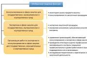
The specialist who is responsible for must:
- inspect TT, check the mode of its operation;
- monitor the preparation of TT for examination, conduct all the necessary document flow;
- issue instructions when detecting violations in work;
- monitor compliance with industrial safety rules, own regulations or orders government agencies, as well as repair, reconstruction of the system;
- take part in examinations, surveys;
- control the conduct of emergency training;
- upon identifying violating workers, demand their removal from work and sending them to an extraordinary examination of knowledge.
The second employee is the specialist responsible for safe operation. His responsibilities include:
- ensuring the operability, repair, preparation of TT for technical examination, diagnostics;
- monitoring compliance by workers;
- conducting and participating in periodic inspections, technical surveys of the system;
- storage of all technical documentation of TT (registration certificate, instructions for installation, use, manuals), checking entries in the shift log;
- counter-emergency training of employees;
- compliance with all instructions to eliminate the identified violations;
- keeping records of CT load cycles, if they are operated in a cyclic mode.
The safe operation of pipelines is achieved by their correct laying, high-quality installation, installation of expansion joints and the necessary fittings, the device, if necessary, heating and drainage, monitoring their technical condition and timely repair.
Pipelines should have a signal color depending on the type of working fluid:
Water is green;
Steam is red;
Air is blue;
Flammable and non-flammable gases - yellow;
Acids - orange;
Alkalis - purple;
Flammable and non-combustible liquids - brown;
Other substances are gray.
To highlight the type of hazard, color signal rings are applied to the pipeline. Red rings mean that explosive, flammable, flammable substances are being transported; green - safe or neutral substances; yellow - toxic substances. In addition, yellow rings indicate other hazards (high vacuum, high pressure, radiation). The number of warning rings corresponds to the hazard level of the substance being transported. Together with colored signal rings, warning signs, marking plates and inscriptions on pipelines located in dangerous places are also used.
The detection of the appearance of gas in the air of the working area is facilitated by giving it a smell. Piping should be routed with some * slope, but lowered sections and dead ends where liquids remain should be avoided. Steam pipelines and gas pipelines in which condensate can form must have drainage devices to remove condensate and water.
In order to facilitate the repair and installation of flange connections, they should be located in convenient places. It is forbidden to place them over walkways, workplaces, over electrical equipment. Each flange connection on a pipeline carrying chemicals must have a protective cover to prevent the release of a jet of hazardous material under pressure.
In order to prevent the occurrence of dangerous thermal stresses (which can cause breaks during cooling or bending during heating of pipes, detachment of flanges), compensating elements are provided on the pipelines. Compensation of thermal stresses is ensured by the use of expansion joints or by arranging self-compensating pipelines.
When the route of the pipeline is a broken line, then self-compensation is provided by means of movable supports. Compensators are made of bent pipes in the form of letters P, U, lyre. Spiral, lens compensators are also used. Compensators are made of elastic materials.
The pipelines must have serviceable and adjusted check, pressure reducing, shut-off, safety valves. Check valves allow gas or liquid to pass only one way. Check valves of pressure vessels, including pipelines, prevent the backflow of the working fluid in the event of combustion and in the event of a reaction (Fig. 3.1).
The pressure reducing valves maintain the set pressure (Fig. 3.2).
Safety valves are an important element of the pipelines. They are used to prevent the occurrence of a pressure in the pipeline that exceeds the allowable value. If the pressure is exceeded through the valves, part of the gas or liquid is released into the atmosphere. The installation of any fittings between the safety valve and the pressure source is prohibited.
The safety valve must be closed with a special casing to prevent unintentional adjustment of the valves by service personnel. After the relief valve has opened, the operator must immediately adjust the pressure.
BASICS OF SAFETY
Section 3
Fig. 3.1. Check valve:
a - lifting: i - body; 2 - spool; 3 - spring; 4 - cover; b - rotary: 1 - body; 2 - bolt; 3 - cover; 4 - earring
The pipelines are periodically subject to external inspection and hydraulic testing. During an external examination, the condition of welded and flanged joints, glands is determined, slopes, deflections, and the strength of supporting structures are checked. A hydraulic test is carried out with a set pressure, depending on the material of the pipeline. The results of the hydraulic test are considered satisfactory if the pressure has not dropped, and no signs of rupture, leakage or fogging are found in the welds, pipes, valve bodies.

Fig. 3.2. Reducing valve: 1 - channel; 2 - spool; 3 - spring; 4
- flywheel; 5 - piston
The most common designs of direct-acting relief valves are shown in fig. 3.3.

Fig. 3 3. Schematic diagrams of direct-acting safety valves:
i - magnetic spring; b - spring with ejection device;
c - with a differential piston