


 , cm
, cm , cm
, cm , cm
, cm , cm
, cmRate of return ratios
At a certain price level, a reduction in costs leads to an increase in income, i.e., the reverse side of costs...
Page 6
Table - Number of types of corners
Calculation of truss nodes
The truss rods in the nodes are connected by sheet gussets, to which they are attached using electric welding.
Determined by the formula
![]()
The length of the seam along the feather is determined by the formula
![]()
where α is a coefficient that takes into account the share of force on the butt
N - force in the rod, kN
βf-penetration coefficient (at manual weldingβf=0.7)
Kf1, Kf2 - thickness of seams along the butt and along the feather, respectively, cm
Rwf is the calculated resistance of fillet welds to shear metal,
equal when using E50 type electrodes: Rwf= 21 kN/cm2
γwf - coefficient of weld operating conditions; γwf=1
The coefficient α is taken equal to: for equal angles α=0.7.
The thickness of the seam along the edge of the corner is taken to be 2 mm less than the thickness of the flange of the corner, but not less than 4 mm. The maximum thickness of the seam along the edge of the corner should not exceed 1.2t min, where tmin is the thickness of the thinner element (the gusset or flange of the corner).
The minimum joint length should be 4 Kf or 40 mm. The maximum design length of the seam should not exceed 85βf Kf.
Let us determine the lengths of the seams of the belts “6” and “7” (δ=6mm):
Structural seam length along the back
We take lw1 = 22 cm.
Feather seam length
Kf1 = 8mm = 0.8cm. Kf2 = 6 mm = 0.6 cm.
Let us determine the lengths of the belt seams “30” and “26” (δ=6mm):
Structural seam length along the back
We take lw1 =4 cm.
Feather seam length
![]()
Kf1 = 8 mm = 0.8 cm. Kf2 = 6 mm = 0.6 cm.
Let's determine the length of the seams of the belt “22” (δ=6mm):
Structural seam length along the back
We take lw1 =4 cm.
seam length along feather
Kf1 = 8 mm = 0.8 cm. Kf2 = 8 mm = 0.8 cm.
The calculated lengths of the seams are plotted on the knot diagram, after which the dimensions of the gusset and its outline are revealed. The adopted outline of the gusset should be simple, preferably rectangular.
Node E must have a support rib of 16…25mm. Minimum rib width 180 mm.
Table welds at farm nodes
The dialog box will look like this.
The dialog box offers nine types of most commonly used composite sections (sections can be selected in the Section Type field at the top right of the dialog box):
– two channels placed face to face or back to back;
Two I-beams;
Channel and I-beam (the channel is placed facing or with its back);
Two corners and an I-beam;
Four corners pen to pen;
Four corners back to back;
Two corners connected in a T shape, shoulder to shoulder, with short or long sides;
Two corners joined in a C shape, feather to feather, short or long sides;
Two corners connected in the shape of a cross.
For some types of composite sections, the Composite sections - welded option is available; if the option is active, then the chords of the composite section are assumed to be welded along the length of the section.
Defining a Composite Section Family.
In order to define a family (group) of composite sections, the user must:
Note Some types of sections (for example, 4 corners) require the definition of two different sections of chords and two different distances between chords depending on the grid plan (b,d).
Compound Section Creation Method.
The program automatically creates a family of composite sections based on the initial data defined by the user. The first composite section in a family of composite sections is made up of two initial sections located at a distance d. Successive composite sections are formed without changing the cross-sectional dimensions of the chords by increasing the distance d by the increment dd until the value dmax is reached. After this, the program automatically increases the chord section by one size and forms new composite sections, starting again with step d and continuing to increase the step until the value dmax is reached. The program generates sections until it reaches the end of the database, that is, until the possibility of selecting new sections is exhausted.
Composite section.
Belt section (initial section) - C240
Distance between belts - d=25 cm
Step increment dd = 5 cm
Maximum step dmax = 30 cm
The program will create a section family with a name, for example, 2CF, containing 9 sections. When the generation of sections is completed, the last section of the C-section family will be section C300. The resulting sections are presented below.
The calculated force in a section of paired equal angles is distributed as follows: 70% falls on the butt (i.e. N about = 0,7N) and 30% - for the pen (i.e. N n = 0,3N).
When calculating welds, the values of the seam legs along the butt are specified (
) and by pen (  ) and determine the required lengths of seams along the back (
  ) and by pen (
  ).
).
When assigning a suture leg, the following recommendations must be taken into account:

(corner or gusset). The thickness of the gussets is determined according to the table. 13 adj. 2.
The required length of the weld along the butt is taken according to the largest value found using the formulas:
when calculating weld metal
 ;
(4.4)
;
(4.4)
 ,
(4.5)
,
(4.5)
Where γ wf = γ wz = 1 (clause 11.2*) – coefficients of operating conditions of the weld;
f = 0,7, z = 1 (Table 34*) – penetration depth coefficients corresponding to semi-automatic welding in the lower position;
 (Table 6*) – coefficient of operating conditions of the structure;
R wf And R w z(see paragraph 2) – calculated shear resistance of the connection with fillet welds.
The required length of the weld along the feather is taken according to the largest value found using the formulas:
when calculating weld metal
 ;
(4.6)
;
(4.6)
when calculating metal fusion boundaries
 .
(4.7)
.
(4.7)
 When assigning lengths of welds along the butt (
  )
and by pen (
)
and by pen (  ) should be guided by the following:
1.
 -
integer number of centimeters;
-
integer number of centimeters;
2.
 ≥ 4
cm;
≥ 4
cm;
3.
 ;
;
4.
 ;
;
5. values
 And
And
 take as little as possible.
Rice. 2. To the calculation of welds
The detail (working) drawing shows the facade of the truss, plans for the upper and lower chords, and a side view. The nodes are depicted on the facade, and for clarity of the drawing, the nodes and sections of the rods are drawn on a scale of 1:10 on the diagram of the truss axes, drawnnoah on a scale of 1:20.
Grating rods are usually cut normal to the axis of the rod. For large rods, oblique cutting is allowed to reduce the size of the gussets. The grille rods are not brought to the distance from the belts a = 6 t f – 20mm(Where t f – gusset thickness in mm), but not more than 80 mm(Fig. 2).
In a truss with rods made of paired angles formed by a brand, the nodes are designed on gussets that are inserted between the angles. It is recommended to attach the gussets to the truss belt with continuous seams of minimum leg length. The gussets are released behind the edges of the waist corners at 10...15 mm(Fig. 2).
The basis for designing truss nodes is the intersection of the axes of all the rods converging in the node in the center of the node. The main dimensions of the unit are the distances from the center of the unit to the ends of the attached lattice rods and to the edge of the gusset. Based on these distances, the required length of the lattice rods is determined, which is assigned as a multiple of 10 mm, and the sizes of the gussets. The dimensions of the gussets are determined by the required length of the seams for fastening the elements. It is necessary to strive for the simplest outlines of the gussets in order to simplify their production and reduce the number of trimmings.
To ensure that the corners work together, they are connected with gaskets. The clear distance between the gaskets should be no more than 40 i x for compressed elements and 80 i x for stretched ones, where i x – radius of inertia of one corner relative to the axis x - x. The thickness of the gaskets is assigned equal to the thickness of the nodal gussets. Spacers are accepted with a width of 60 mm and are produced for corner dimensions of 10...15 mm in each direction.
On the façade of the truss the dimensions (legs and lengths) of the welds are indicated.
Take the base plate with a thickness of 20 mm and dimensions in plan 300 x 300 mm.
The drawing contains a specification of parts (according to the established form) for the truss and provides notes.
APPENDIX 1
Table 1
Initial data for students of specialty 270301 "Architecture"
|
The last two digits of the cipher |
Truss length L(m) |
Truss spacing |
Truss height h(m) |
Steel grade |
|
Table 2
Initial data for students of specialty 270302 "Architectural Environment Design"
|
The last two digits of the cipher |
Truss length L(m) |
Truss spacing |
Truss height h(m) |
Steel grade |
|
APPENDIX 2
Table 3
Standard and calculated tensile strengths,
compression and bending of rolled products according to GOST 27772-88 for steel
structures of buildings and structures (sample from table 51* 2)
|
rolled, mm |
Standard resistance of shaped rolled products, MPa |
Design resistance shaped steel, MPa |
|||
|
R ун |
R un |
R at |
R u |
||
|
St. 20 to 40 | |||||
|
St. 20 to 30 | |||||
|
St. 10 to 20 St. 20 to 40 | |||||
|
St. 10 to 20 | |||||
|
St. 10 to 20 | |||||
|
St. 10 to 20 St. 20 to 40 | |||||
|
St. 10 to 20 St. 20 to 40 | |||||
Table 4
Welding materials and design resistances
(sample from tables 55* and 56)
Table 5
Hot-rolled steel I-beams with sloped internal flange faces (GOST 8239-89)
|
Dimensions, mm |
cross-section, cm 2 |
Axis x – x |
Axis y - y |
Weight 1 m, kg |
|||||||||
|
I x, cm 4 |
W x, cm 3 |
i x, cm |
S x, cm 3 |
I y , cm 4 |
W y, cm 3 |
i y, cm |
|||||||
Table 6
Hot-rolled steel channels with sloped internal flange faces (GOST 8240-89)
|
Dimensions, mm |
cross-section, cm 2 |
Axis x – x |
Axis y - y |
z 0 , |
Weight 1 m, kg |
|||||||||||
|
I x, cm 4 |
W x, cm 3 |
i x, cm |
S x, cm 3 |
I y , cm 4 |
W y, cm 3 |
i y, cm |
||||||||||
T  table 7
Hot rolled equal flange steel angles (GOST 8509-86)
Designation: b – shelf width; t – shelf thickness; R – radius of internal curvature; r – radius of curvature of the shelf; I – moment of inertia; i – radius of gyration; z 0 – distance from the center of gravity to the outer edge of the shelf
|
Dimensions, mm |
cross-section, cm 2 |
Reference values for axes |
Weight 1 m, kg |
||||||||||
|
x – x |
X 0 - X 0 |
at 0 – y 0 |
X 1 - X 1 |
||||||||||
|
z 0 |
I x, cm 4 |
i x, cm |
I x 0 , cm 4 |
i x 0 , cm |
I y 0 , cm 4 |
i y 0 , cm |
I x 1 , cm 4 |
||||||
Continuation of table 7
End of table 7

Rice. 3. Determination of forces in truss elements graphically (Maxwell-Cremona diagram)
Table 8
Stability factor
|
Conditional flexibility |
Stability factor |
Conditional flexibility |
Stability factor |
|
Note.
For intermediate values size should be determined by linear interpolation.
Table 9
Vertical maximum deflections of structural elements
(sample from table 19)
Note.
For intermediate values l in pos. 2, A size n 0 should be determined by linear interpolation.
Table 10
Selection of cross sections for truss rods
|
Rod no. |
Design force N, kN |
Sectional area A, cm 2 |
Effective length l x, cm |
Radius of inertia i x, cm |
Flexibility λ |
Ultimate flexibility [ λ ] |
Conditional flexibility |
Stability factor |
Working conditions coefficient γ With |
Section check,
|
||||
|
stretching |
strength
|
sustainability
|
||||||||||||
|
Upper belt |
) ┘└ 12512 |
21,51 < 23,75 |
||||||||||||
|
Lower belt |
23,66 < 23,75 | |||||||||||||
|
constructively |
15,68 < 23,75 | |||||||||||||
|
23,748< 23,75 | ||||||||||||||
|
┘└ 10010 | ||||||||||||||
Table 11
Calculation of welds
|
Rod no. |
Effort N, kN |
Seam along the hem |
Feather seam |
|||||
|
N about , kN |
|
|
N n , kN |
|
|
|||
|
┘└ 10010 | ||||||||
Table 12
Minimum seam lengths (Table 38*)
|
Type of connection |
Type of welding |
Yield strength, MPa |
Minimum legs k f, mm, with the thickness of the thicker element being welded t, mm |
|||||
|
T-shaped with double-sided fillet welds; lap and corner | ||||||||
|
St. 430 to 530 | ||||||||
|
Automatic and semi-automatic | ||||||||
|
St. 430 to 530 | ||||||||
|
T-shaped with one-sided fillet welds | ||||||||
|
Automatic and semi-automatic | ||||||||
Table 14
Design lengths of bars
(sample from table 11)
Designation: l – distance between node centers
Table 15
Ultimate flexibility of rods
(sample from tables 19* and 20*)
Table 16
Working conditions factor
(sample from table 6*)
L I T E R A T U R A
1. SP 53-102-2004. General rules design of steel structures. Gosstroy of Russia.- M.: TsNIISK im. Kucherenko, 2005.
2. SNiP II-23-81 *. Steel structures. Design standards / Ministry of Construction of Russia. - M.: GP TsPP, 2000. - 96 p.
3. SNiP 2.01.07-85 *. Loads and impacts / Gosstroy of Russia. - M.: FSUE TsPP, 2004.-44 p.
4. Faybishenko V.K. Metal structures: Textbook. manual for universities. – M.: Stroyizdat, 1984. - 336 p.
|
General information………………………………………………………..…………………… | |
|
1. Initial data………………………………………………………… | |
|
2. Selection of main design characteristics…………………………… | |
|
3. Calculation of the coating run…………………………………………………………………… | |
|
4. Design of a roof truss……………………………………. | |
|
4.1. Determination of loads on the truss……………………………………….. | |
|
4.2. Determination of design forces in truss rods…………………... | |
|
4.3. Selection of sections of truss rods……………………………………………………… | |
|
4.4. Calculation of welds for attaching braces and struts to gussets...... | |
|
Applications…………………………………………………………………………………... | |
|
Literature……………………………………………………………………. |
Table - Number of types of corners
Calculation of truss nodes
The truss rods in the nodes are connected by sheet gussets, to which they are attached using electric welding.
Determined by the formula
The length of the seam along the feather is determined by the formula
![]()
where α is a coefficient that takes into account the share of force on the butt
N - force in the rod, kN
βf-penetration coefficient (for manual welding βf=0.7)
Kf1, Kf2 - thickness of seams along the butt and along the feather, respectively, cm
Rwf is the calculated resistance of fillet welds to shear metal,
equal when using E50 type electrodes: Rwf= 21 kN/cm2
γwf - coefficient of weld operating conditions; γwf=1
The coefficient α is taken equal to: for equal angles α=0.7.
The thickness of the seam along the edge of the corner is taken to be 2 mm less than the thickness of the flange of the corner, but not less than 4 mm. The maximum thickness of the seam along the edge of the corner should not exceed 1.2t min, where tmin is the thickness of the thinner element (the gusset or flange of the corner).
The minimum joint length should be 4 Kf or 40 mm. The maximum design length of the seam should not exceed 85βf Kf.
Let us determine the lengths of the seams of the belts “6” and “7” (δ=6mm):
Structural seam length along the back
We take lw1 = 22 cm.
Feather seam length
![]()
Kf1 = 8mm = 0.8cm. Kf2 = 6 mm = 0.6 cm.
Let us determine the lengths of the belt seams “30” and “26” (δ=6mm):
Structural seam length along the back
We take lw1 =4 cm.
Feather seam length
![]()
Kf1 = 8 mm = 0.8 cm. Kf2 = 6 mm = 0.6 cm.
Let's determine the length of the seams of the belt “22” (δ=6mm):
Structural seam length along the back
We take lw1 =4 cm.
seam length along feather
![]()
Kf1 = 8 mm = 0.8 cm. Kf2 = 8 mm = 0.8 cm.
The calculated lengths of the seams are plotted on the knot diagram, after which the dimensions of the gusset and its outline are revealed. The adopted outline of the gusset should be simple, preferably rectangular.
Node E must have a support rib of 16…25mm. Minimum rib width 180 mm.
Table of welds in truss nodes
The total estimated length of the welds (cm) attaching the horizontal overlay to the flanges of the corners on one side of the joint:

where N is the force in the lower chord rod pushing towards the mounting unit, kN.
More detailed information on the designs of truss truss units and the features of their calculation should be found in the recommended literature (1); (5); (7).
The result of designing a truss is the preparation of a metal specification for the starting element, the shape of which should be taken according to the textbook (1).
5.Calculation of the transverse frame of the frame
Determination of loads on the frame.
Loads act on the frame
a) constant - from the own weight of the structures
b) short-term: snow; crane - vertical from the pressure of the wheels of the overhead crane and horizontal from the braking of the trolley; wind

Rice. Frame
A) Constant load on the frame. The support reaction of the crossbar (kN) Vg=g1L/2 will act on the frame post, where L is the span of the crossbar (truss); g1 – linear design load, kN/m2
Vg=23.88·24/2=286.56 kN
b) Snow load on the frame. The frame support will be subject to the corresponding support reaction of the crossbar (kN) Vр=S1L/2, where S1 is the linear design snow load, kN/m2
Vр=4.2·24/2=50.4 kN
Vertical crane loads. The crane load on the transverse frame is determined from two close cranes located in such a way that the load is greatest.
Estimated vertical force (kN) acting on the rack (column) to which the crane trolleys are close
Dmax=γf nc Fn max Σyi+G,
where Fn max is the highest wheel pressure
γf - load reliability factor, γf=1.1
Σyi is the sum of the influence ordinates for the support pressure on the column
nc – combination coefficient: nc=0.85
G - weight of the crane beam, kN
Influence line ordinates y1=0.267, y2=1; y3=0.8; y3=0.066.
Dmax=1.1·0.85·315·(0.267+1+0.8+0.066)+10.5 =717.36 kN
Design vertical force acting on another frame leg
Dmin=γf nc Fn min Σyi+G,
where Fn min is the lowest wheel pressure on the valve (kN)
Fn min=(P+Gc)/n0- Fn max
P - crane lifting capacity
Gc - total weight of the crane with trolley
n0- number of wheels on one side of the crane n0=2
Fn min=(300+520)/2- 315=95 kN
Dmin=1.1·0.85·95·2.4+10.5=223.68 kN
Horizontal crane loads.
Design horizontal force (kN)
Tc= γf·nc·Tn·Σyi,
where Tn is the standard horizontal force when braking the trolley,
per one wheel of the crane.
The horizontal force Tc can act on the left or right pillar of the frame, in both one and the other direction.
At a certain price level, a reduction in costs leads to an increase in income, i.e., the reverse side of costs...
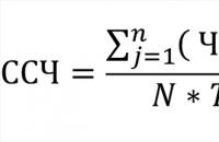
The government has made a decision that all accountants will experience for themselves in 10 days. Namely: now, in addition to SZV-M...
It will be necessary to calculate the average headcount for 2016 in several cases. Firstly, to fill out the information...

Any enterprise operates in a macro- and microenvironment. It has a whole range of resources that are used in...

Methodological development of a literary reading lesson in 3rd grade (UMK “School of Russia”) “L. N. Tolstoy “Shark” Work on...

Information technologies are penetrating various areas of business at such a speed that it is sometimes difficult to assess their relevance....

A damp, cold wind blew from the sea, carrying across the steppe the thoughtful melody of the splash of a wave running onto the shore and...

Quality, quality, quality... How differently this concept is perceived and defined! In Fig. 1...

On September 13, 2012, in connection with the retirement of Stanislav Vladimirovich Khramenkov, the new general...

The history of pottery knows two main types of pottery wheels - hand and foot. Both of them work...

Every year hundreds of nurses study to become cosmetologists. After training with people with secondary medical education. There are three education...
Kazakova Daria, Emelyanova Ksenia, Sidorin Andrey Relevance of the topic: every little child loves it when...

The Gazprom Corporation is one of the largest players in the Russian and global economy. How is it organized...

Modern Russian culture of the 21st century requires multilateral and in-depth consideration. She is in close contact with...
The government has made a decision that all accountants will experience for themselves in 10 days. Namely: now...
It will be necessary to calculate the average headcount for 2016 in several cases. Firstly, to fill out...