354 resolution current edition
A citizen of the Russian Federation (each individual) is a consumer of state resources: water (for hot and cold), electricity, etc....
For open mining and exploration workings, justify the method of excavation, the equipment used and in accordance with the angle of repose rocks choose and justify the shape and dimensions cross section taking into account the design depth of the mine.
For underground mining and exploration workings, justify the excavation method and the corresponding mining equipment, select and justify the shape and dimensions of the cross-section of the working in the open.
Depending on the physical and mechanical properties of rocks, as well as based on the dimensions of the transport and technological equipment(electric locomotives, trolleys, loading machines) taking into account the size of the gaps provided for by the safety rules (Safety Rules) during geological exploration work, the cross-sectional dimensions are determined mine workings in the light. The dimensions of the openings in the tunneling are determined taking into account the thickness of the support and tie rods, as well as the height of the track device (ballast, sleepers, rails).
Mining can be carried out with or without support. Wood, concrete, reinforced concrete, metal and other materials are used as fastening materials. The cross-sectional shape can be: rectangular, trapezoidal, vaulted, round, elliptical.
Horizontal and inclined exploration workings, as a rule, have a short service life, so the main type of support is wood, the cross-sectional shape is trapezoidal. When driving without fastening, the cross-sectional shape is rectangular-vaulted.
For a trapezoidal cross-section of a mine working with rail transport ( rice. 1) it is recommended to calculate the cross-sectional area of the mine in the following sequence.
Based on the dimensions (width and height) of the electric locomotive or trolley used (for manual hauling), the clear width of the single-track excavation is determined at the level of the edge of the rolling stock:
B = m + A + n`
and the width of the double-track mine:
B = m + 2A + p +n`
m– size of the gap at the level of the edge of the rolling stock, mm(taken equal to 200 – 250 mm);
p– gap between compounds, mm (200mm);
n`- the size of the passage for people at the level of the edge of the rolling stock, mm:
n` = n + * ctg ;
n– passage size at an altitude of 1800 mm from the level of the ballast layer, equal to at least 700 mm;
h – height of the electric locomotive (trolley) from the rail head, mm;
h a- height of the track superstructure from the ballast layer to the rail head, equal to 160 mm;
83 0 – angle of inclination of the racks, adopted according to GOST 22940-85 for exploration workings.
The height of the working from the rail head to the top in the case of using contact electric locomotives (before the support settlement):
h 1 = h kp. + 200 + 100,
h kp.– height of the contact wire suspension (not less than 1800 mm);
200mm– gap between the contact wire and the support;
100mm– the amount of possible settlement of the support under the influence of rock pressure.
For other types of transport, height h 1 determined by graphical construction taking into account the gap C between transport equipment and the ventilation pipeline: when transporting by battery electric locomotives 250 mm, with manual rollback - 200 mm.
When transporting by battery electric locomotive:
h 1 = h + d t + 250 + 100,
Where h – electric locomotive height, mm;
d t- diameter of the ventilation pipeline, mm.
Height h 1 in general, it should not be less than the height of the loading machine with the bucket raised (for PPN-1s this height is 2250 mm) minus the height of the ballast layer, i.e. h 1 2250 mm.
Width of excavation in the clear along the ballast layer:
l 2 = B + 2(h + h a) * ctg ;
Clear opening width along the roof:
l 1 = B – 2(h 1 - h) * ctg ;
The height of the excavation from the ballast layer to the support after settlement:
h 2 = h 1 + h a;
Cross-sectional area of the excavation in the clear after settlement:
S St = 0.5(l 1 + l 2) * h 2;
Width of the rough working on the roof (when fastened staggered with tightening of the sides):
l 3 = l 1 + 2d,
Where d – diameter of the support post (not less than 160 mm).
The width of the excavation along the rough soil when fastened staggered with tightening of the sides:
l 4 = B + ![]() ,
,
where h V= 320mm– height from the excavation soil to the rail head:
h c = h a + h b,
Where h b – height of the ballast layer.
Height of excavation from soil to support (before settlement):
h 3 ` = h 3 + 100,
Where . h 3- the height of the excavation from the soil to the top (after settlement).
Height of roughing before settlement in the presence of tightening:
h 4 ` =h 3 ` + d + 50,
Where d– diameter of the scaffolding, mm;
50mm– tightening thickness.
Height of excavation after settlement:
h 4 = h 4 ` - 100
Cross-sectional area of the excavation rough before settlement:
S 4 = 0.5(l 3 + l 4) * h 4 `
Vertical draft equal to 100 mm, is allowed only with wooden support.
In the workings they use the laying of wooden sleepers and laying the track from rails P24 for trolleys with a capacity of up to 2 m 3. When carrying out exploration workings, trolleys are used VO-0.8; VG-0.7 And VG-1,2 capacity respectively 0.8; 0.7; 1.2 m. When manually hauling trolleys VO-0.8 And VG-0.7, as well as AK-2u electric locomotives use rails P18. The sleepers are laid in a ballast layer with a thickness of 160 mm, immersing them to 2/3 of its thickness.
With a rectangular-vaulted shape, the clear height of the excavation consists of the height of the wall from the level of the ballast layer and the height of the arch ( rice. 2).
Rough working height H determined as the clear height plus the thickness of the support in the vault with monolithic concrete support or plus 50 mm with shot concrete, anchor (rod) and combined support. Wall height from the level of the rail head to the heel of the arch h 1 when transported by battery electric locomotives, it is determined depending on the height of the electric locomotive. The height of excavations during transportation by contact electric locomotives must satisfy the conditions under which minimum gaps are ensured between the electric locomotive (trolley) and the support, as well as between the pantograph and the support.
The height of the vertical wall from the level of the tapa to the heel of the arch h 2 = 1800mm. Vault height h 0 accepted depending on the rock strength coefficient on the M.M. scale. Protodyakonov.
For monolithic concrete lining with a strength coefficient f =3:9, h 0 = B/3.
For shot-concrete and anchor support and in workings without support f 12 ,h 0 =B/3, and when f 12, h 0 =B/4.
The curve of a three-center (box) vault is formed by three arcs: axial - R and two side ones - r. Radius of the arch depending on its height:
| Arch height | h 0 | B/3 | B/4 |
| Axial arc radius | R | 0,692 | 0,905 |
| Side arc radius | r | 0,262 | 0,173 |
Design working width B 1 for concrete support it consists of the clear width of the excavation and twice the thickness of the support, and for shot concrete, anchor and combined support - from the clear width of the excavation plus 100 mm.
Clear width of single-track excavation:
B = m + A + n
Clear width of double-track excavation:
B = m + 2A + p + n,
Where n= 700mm; p = 200mm.
Height of the vertical wall of the excavation from the rail head:
h 1 = h 2 – h a = 1800 – 160 = 1640mm.
Width of rough working with shot-concrete and anchor support:
B 1 = B +2 = B + 100,
Where = 50mm– thickness of the support taken in the calculation.
The cross-sectional area of the excavation in the light at the height of the arch h 0 = B/3:
S St. = B (h 2 + 0.26B),
at h 0 = B/4: S St = B (h 2 + 0.175B),
Where h 2 = 1800mm - height of the vertical wall from the level of the ladder (ballast layer).
Height of the wall from the excavation soil:
h 3 = h 2 + h b = h 1 + h B.
Production parameter in light at h 0 =B/3:
P B = 2h 2 + 2.33B,
at h 0 =B/4: .P B = 2h 2 +2219B
Cross-sectional area of rough excavation with shot-concrete, anchor, combined lining with h 0 =B/3:
S h = B 1 (h 3 + 0.26B 1),
at h 0 =B/4: S h = B 1 (h 3 + 0.175B 1).
After determining the cross-sectional area, we take according to GOST 22940-85 the nearest standard section and write down its dimensions for further calculations. According to this standard, only the clear cross-sectional area of the excavation is determined, and the rough cross-sectional area is determined depending on the adopted cross-sectional shape, type and thickness of the support according to the above formulas.
In the table 1 Typical sections and basic equipment adopted when calculating the clear cross-section are given, as well as the dimensions of basic vehicles.
The depth of the pits is conventionally divided into small ones (up to 5 m), medium (5 – 10) and deep (up to 40 m). The depth of the pits depends on the stage of exploration and geological conditions. Depending on the physical and mechanical properties of the rocks, the method of excavation and the design of the support, the pits are round and rectangular in shape. As the hole depth increases, the clear cross-sectional area increases. Pits up to 10 deep m usually have one compartment, and with a depth of up to 20 m may have two compartments. Typical sections ( GOST 41-02-206-81), it is planned to drill holes with a clear cross-sectional area from 0.8 to 4 m 3 and geometric dimensions (Table 2).
Introduction
During the period of general economic decline and inflation in the country, national production problems worsened coal.
Coal is the main type of energy fuel, as well as technical raw materials for coking and use in metallurgical and chemical industry for the production of liquid and gaseous fuels.
In terms of coal reserves, Russia ranks one of the first places in the world, and the Kuzbass coal basin is the first place in Russia in coal production.
The workers of the coal industry are faced with the task of steadily increasing coal production while simultaneously reducing its cost, the solution of which is an indispensable condition for survival in today's economic conditions.
To achieve its goals, the coal industry focuses its efforts on the following areas: constantly work on issues of integrated mechanization and automation production processes, which creates the prerequisites for extracting coal without the constant presence of people at the mining face, which helps to increase labor productivity and reduce the cost of mined coal.
A further increase in coal production is closely related to the pace of development work. Systems need to be applied more widely and everywhere automated control production processes in the development faces for timely and high-quality preparation of the production front. The choice of optimal technological schemes for carrying out workings is an indispensable condition for highly productive and safe work in development faces, the purpose of this course project is to develop a passport for the installation and fastening of a ventilation drift.
1 MINING AND GEOLOGICAL CHARACTERISTICS OF THE Breevsky FORMATION
The depth of development of the seam is 350-490m.
The seam has a complex structure, consists of 3 coal packs, separated by rock layers with a thickness of 0.04 m to 0.25 m, represented by highly fractured mudstone, weak and medium thickness f = 2.5 - The total thickness of the seam ranges from 2.1-2 .15 m and with an average thickness of 2.12 m.
In the seam there are inclusions of “pyrites”, strength f = 7-8, elongated oval shape with dimensions up to 2x0.5x0.5, confined to the middle part of the coal seam.
The hypsometry of the formation is wavy. The dip angle of the formation is from 16 0 (at the ventilation drift No. 173) to 0 0 (at the installation chamber No. 1732).
The natural gas content of the formation is 8-13 m 3 /t.
Coal strength f= 1.5-2, Coal cutting resistance 15 MPa.
According to the formation's tendency to spontaneous combustion, it belongs to group III of non-hazardous ones. Dangerous due to the explosiveness of coal dust and methane gas.
The layer is represented by shiny coal with a predominance of vitrinite group components. The upper interval of the main roof of the formation is represented by fine-grained, strong, fractured sandstone, up to 12 m thick, f = 6-7.
The lower interval of the main roof of the formation with a thickness of up to 4 m is represented by fine-grained sandstone, strong f = 6-7, layered fractured mudstone with a thickness of up to 2 m, f = 3-4 with a coal layer in the upper part up to 1 meter thick (Nadbreevsky formation).
The initial step in the collapse of the main roof is 35-40 m of lava withdrawal from the mounting chamber, the subsequent step is 8-12 m.
The immediate roof of the formation is represented by dark gray argillite, layered of medium strength, fractured, up to 8 m thick, f = 3-4. The lower limit of the immediate roof at a thickness of 0.35-0.85 m, taking into account the “false” roof, is represented by weak argillite with coal interlayers with a thickness of 0.05-0.2 m and prone to vaulted collapse at the full thickness of the roof.
The false roof is represented by dark gray, fractured mudstone, with a thickness of 0.30-0.80 m f = 1.5-2.
The immediate soil of the formation is represented by fine-grained siltstone, medium strength, fissured, up to 8 m thick, f= 4.
False soil is represented by light gray mudstone, strength f=2. The thickness of false soil varies from 0.08 to 0.15 m, with an average thickness of 0.10 m. When wet, it is prone to heaving.
Tectonically, the area is simple, but the possibility of encountering small-amplitude disturbances (up to 1.5 m) cannot be ruled out.
2.Choice of cross-sectional shape and type of mine support.
This project considers the installation of a conveyor furnace, which is designed to transport rock mass and pass a ventilation stream. Scientific and practical experience has established the low efficiency of arched and rack supports.
These types of supports do not carry a pre-load, do not strengthen the roof of the excavation, are labor-intensive to install, are costly, and have a small area of application in terms of effectiveness. Moreover, the time factor reduces the stability of the support and significantly complicates the work of powered supports during mining.
In world practice, various types of anchor supports are widely used, which provide varying degrees of strengthening of the rocks of the mine arch, thereby eliminating the collapse of rocks. Based on this, we accept the anchorage of the excavation, and the cross-sectional shape is rectangular.
Determination of the dimensions and cross-sectional area of the excavation.
This project considers the construction of a ventilation drift, which is designed to transport rock mass and pass a ventilation stream
The cross-sectional area of the drift in the clear is determined by calculation based on the permissible speed of the air stream, the overall dimensions of the rolling stock, taking into account the minimum permissible gaps, and the amount of support settlement after exposure to rock pressure. A distinction is made between the cross-sectional area of the excavation in the open - this is the cross-sectional area inside the contour of the excavation support; - the cross-sectional area of the excavation in the tunnel - this is the cross-sectional area of the excavation without taking into account the support. According to PB requirements, the minimum cross-sectional area of a conveyor drift is 6.0 m2, the minimum height is 1.8 m.
The clear width of the excavation at a height of 1.8 m is determined by the formula
B sv = m + A 1 + n m
where: In St - the clear width of the excavation, m;
A 1 - dimensions of the monorail container, m
n is the gap between the container and the support on the running side, m
m is the gap between the container and the support on the non-travel side, m
B sv = 0.3+1.4+0.85=2.95 m
Rice. 1. Cross section of the excavation
Based on the resulting width of the excavation, we take the typical cross-section in the tunneling S st = 13.9 m 2 , S prox = 14.0 m 2 .
The dimensions of a typical section are summarized in Table 2.6.1
We check the accepted cross-sectional area of the mine using the maximum permissible air velocity using the formula:
V = Q/ 60*S light m/sec
where: V is the air speed passing through the workings, m/sec
Q is the amount of air passing through the workings, m 3 /min.
V = 4000 /60*13.9= 926.66 m 3 /sec.
The resulting air speed meets the requirements of the safety regulations, V min = 0.25 m/sec. V max 4 m/s
Table 2.6.1 Dimensions of cross-section of the roadway
Calculation of support.
Selection of support material
The choice of support material is made based on the intended service life of the excavation, the magnitude and direction of the head pressure, the shape of the cross-section of the mine opening, the design of the support, and the requirements of safety rules.
Fastening materials must meet the following basic requirements: have high strength, be stable over time, have low cost, be non-flammable, etc.
Wooden frame support is used with a service life of up to 2 - 3 years in stable and medium-resistant rocks. Metal frame support is used with a service life of up to 10 - 15 years in different geological and mining conditions.
Monolithic concrete and reinforced concrete linings are used in capital workings, and prefabricated reinforced concrete and tubing linings are used in capital and other workings with a long service life and in different geological and mining conditions.
Since the service life of the ventilation drift is up to three years, we accept anchor support in the project
Related information.
The cross-sectional area in the light is the area limited by the internal. The contour of the support and on top of the ballast layer of the rail track (without taking into account the thickness of the support)
Rough sectional area - the area along the outer contour of the support, including the tightening and the soil of the excavation.
The area limited by its design contour is determined by adding the clearance dimensions in the light with the thickness of the support, taking into account the thickness of the tightening and backfilling.
The cross-sectional area of the excavation in the tunnel is the area limited by the contour of the excavation in the face (it is taken to be 3-5% larger than the rough area).
Based on the nature of the connection between solid particles, soils are divided into granular, cohesive and rocky.
Loose, non-cohesive soils are characterized by a lack of cohesion between particles, significant water permeability, low compressibility, high internal friction forces and rapid deformation under load.
Cohesive soils have low water permeability;
The presence of water in them determines the molecular forces of adhesion. Therefore, cohesive soils are characterized by significant cohesion between particles, large deformations under load and duration of deformations.
In rocky soils, their particles are rigidly bound together by a cementing substance, and this bond is not restored if it is broken.
A more complete classification and characteristics of soils are given in reference books and specialized literature.
The properties of soils have a significant impact on the nature of their development and the performance of machines. In this regard, when choosing the type of machine for excavation work, it is necessary to take into account the characteristic properties and condition of the soil being excavated. From this point of view, the most important properties of soils - resistance to development and their stability as a base on which the machine is installed - are determined mainly by the granulometric composition and physical and mechanical properties of the soil.
work, it is necessary to take into account the characteristic properties and condition of the soil being developed.
The most important properties of soils from this point of view - resistance to development and their stability as a base on which the machine is installed - are determined mainly by the granulometric composition and physical and mechanical properties of the soil.
The granulometric composition of soil is characterized by the percentage content by weight of particles of various sizes. The size of individual particles of non-rocky soils is: pebbles 40 mm; gravel 2-40 mm; sand 0.25-5 mm;
If this work does not suit you, at the bottom of the page there is a list of similar works. You can also use the search button
Carrying out mining operations (part 1)
General issues carrying out workings.
Carrying out mining
a complex of processes of mining, loading, transportation of rock mass, construction of support, ventilation, expansion of transport devices and communications. Ensuring the advance of the preparatory face.Method of excavation
a set of technical solutions for breaking, loading rock mass and securing the face, the implementation of which makes it possible to carry out mining in certain mining and geological conditions. Methods of implementation are divided into ordinary and special.Conventional methods methods of carrying out excavations in stable rocks, allowing their exposure for a certain period of time.
Special methods
methods of working in loose rocks and rocks with increased water content.Technological diagram of the development
a specific order in which production processes are carried out, linked in space and time, means of their mechanization and the placement of equipment corresponding to this order.Technological schemes for carrying out workings are divided into:
Homogeneous breed
a rock whose strength is approximately the same throughout the face.Heterogeneous rock
a set of rock layers whose properties differ across the cross-section of the production face. A typical example of a heterogeneous rock of a coal mine with a hairstyle of roof rocks. (soil)Carrying out a continuous slaughter
a scheme for carrying out a working, in which the breaking (excavation) of rocks is carried out simultaneously along the entire face.Carrying out with separate notch
layers of rock or coal and surrounding rock a scheme in which first a coal seam or a certain layer is removed into a certain excavation, and then the host rocks or remaining layers.Carrying out a narrow face
a scheme in which the excavation of rock mass is carried out only within the cross-section of the excavation.Carrying out a wide face
a scheme in which coal is excavated outside the excavation cross-section with waste rock placed in the resulting space.Working section
an image in the drawing on a certain scale of the contour of the excavation, support, equipment, paths and communications, obtained as a result of the intersection of the excavation with a plane. Sections differ in the type of cutting planes. For a longitudinal section, the cutting plane passes along the axis of the excavation. For a cross section, the cutting plane runs perpendicular to the axis of the excavation.Section in penetration
cross-section of the excavation after excavation of the rock mass before installation of support along the contour of the surrounding rocks.Rough section section along the outer contour of the support and the soil of the excavation.
Clear section section after erection of support and laying of the rail track along the internal contour of the support and the top of the ballast layer and, in its absence, along the soil.
The cross-sectional shape of the mine is determined by:
Depending on the cross-sectional shape of the workings, there are: rectangular (a), trapezoidal and polygonal (b-d). Horizontal excavations are usually supported by wood, metal or prefabricated reinforced concrete.
/ used support.The excavations have a vaulted cross-sectional shape (e-m), secured by an arched or/ used support.
Vertical excavations most often have a rectangular (a) or round (n) shape and are secured with concrete or tubing support.
The cross-sectional area of the excavation is determined by:
All clearances are given in §88 PB.
For the movement of people in the excavation, a passage of at least 0.7 m wide is left at a height of 1.8 m from the sidewalk, top of the ballast layer or soil.
The minimum cross-sectional area of the excavation is 4.5 m 2 (§88 PB)
Materials for fastening mine workings.
The following materials are used for supporting mine workings:
Metal for mine support they are used in the form of rolled profiles made of low-alloy or low-carbon steels (Art. 5)
SVP They produce 6 standard sizes with a weight of 1 lm. 14,17,19,22,27, and 33 kg.
In addition to rolled metal, metal tubes are produced - segments having a curved plate (wall) and stiffeners.
Concrete artificial stone material containing binders(cement, gypsum cement), fine aggregate, coarse aggregate and water.
Sand is used as fine aggregate, and durable gravel or crushed stone is used as coarse aggregate.
The composition of concrete is determined by the content by weight of cement, sand (A) and coarse aggregate (B)
1: A: B
And also according to the ratio of the mixed amount of water (W) and cement (C) B/ C
Cement brand compressive strength of a sample in tenths of MPa, made from one part cement and three parts sand at B/ C = 1: 2.5
The most widely used Portland cement grades are 400, 500, and 600 (less often 300)
With a cooking consumption of 1 m 3 concrete less than 200 kg concrete is called lean;
200 250kg average
More than 250kg fat.
Reinforced concrete a single artificial metal-stone material consisting of concrete and metal reinforcement.
Forest materialsare used for fastening excavations with a service life of 2 3 years.
Pine, spruce, fir, cedar, and larch are used to secure excavations.
The main type of wooden support is rud post ø 7 34 cm, length 0.5 7 m.
Lumber : saw cuts, beams, slabs, boards are obtained by sawing ores of posts (logs).
The tensile strength of timber is~ 10 MPa, compression 13 MPa.
Brick grades 150 and 175 are used for fastening excavations; brick density in masonry is 1800 kg/ m 3 .
Betonites concrete stones made from ordinary or silicate concrete and blast furnace slag. Betonite grade not lower than 150.
LECTURE No. 20
Carrying out mining operations (Part 2)
The concept of processes and operations during development work
Process - work clearly defined in its technical and organizational content, consisting of separate parts (operations) performed in a certain sequence.
Operation - a set of working techniques, characterized by constancy of the place of performance and performers.
Basic processes- processes that are carried out directly in the working face and are intended to change the shape and condition of the face (separation of the rock mass from the massif and fastening the face).
Helper Processes- processes that ensure the effective and safe implementation of basic.
Main and auxiliary processes can be performed sequentially or combined.
Based on the possibility of combining in time, they distinguish:
Flow technology is a technology in which the execution of main processes (operations) is combined in time.
Cyclic technology is a technology in which the execution of basic processes (operations) is carried out sequentially.
The boring cycle and its main parameters
Drilling cycle- a set of processes and operations, as a result of which the face moves in a certain time to the distance specified in the passport.
Cycle duration- time during which all basic tasks are performed technological processes tunneling cycle.
The duration of the tunneling cycle is usually taken to be multiple shifts, which simplifies the organization of work.
Face advancement per cycle- the distance to which the face moves after completing all the processes included in the cycle.
Carrying out horizontal and inclined mine workings
in hard and medium hard rocks
Technology of mining in hard rocks f more than 6.7 includes processes:
The following requirements apply to drilling and blasting equipment:
Drilling and blasting parameters are determined for each face individually and are recorded in the drilling and blasting passport.
After drilling and ventilation, the construction of temporary support begins (a structure that ensures safe work in the development face before the construction of permanent support).
To load broken rock mass, special rock-loading machines on caterpillar or wheel-rail tracks are used.
Loading of broken rock mass can be done directly into trolleys or stepwise through specially designed loaders.
Mine support (construction of permanent support)
Depending on the type and material, the support is divided into:
According to their characteristics, supports can be rigid or flexible.
Rigid supports - the total deformation should not exceed the elastic limits. Typically, linings are used in workings with established rock pressure.
Pliable - supports that have special compliance units, due to which the magnitude of the displacements of the support elements exceeds the magnitude of elastic deformations.
Recently, the most widely used roofing bolts have been used to increase the stability of rocks on the roof and sides of a mine by “stitching” several layers together with special rods. The locking part of the anchor is fixed in rocks using metal structures or concrete or polymer compounds.
To secure excavations in areas of heaving rocks, support is used with the addition of a “bed” - an additional element that closes the contour of the support from the soil side.
To prevent rocks from falling out from the roof, a lattice, wooden, polymer or reinforced concrete tie is used.
After completing the main cycle, auxiliary processes begin:
After completion of the auxiliary processes, the tunneling cycle is repeated.
Advantages drilling and blasting method:
Flaws drilling and blasting method:
Combine mining method
The main difference between the combine method of excavation and blasting is the possibility of combining the process of breaking the rock mass and loading it with a road-going machine.
The most common are tracked roadheaders with a swept-type crown-type executive body and a scraper loader.

Scheme of a selective action roadheader. 1 - breaker bit, 2 executive body, 3 - hydraulic jack, 4 - housing, 5 - electrical equipment, 6 - control bullets, 7 - scraper conveyor, 8 - rear support cylinder, 9 - running trolley, 10 - front support cylinder, 11 - loading device.
The use of domestic combines is advisable when carrying out mining operations in a coal seam with a small percentage of rock undercut with a hardness f up to 7 and tilt angle up to -20 0 and up to +20 0 for uprising.
The broken rock mass is loaded onto a scraper or belt conveyor directly by a combine harvester or using a special loader.
Advantages combine method:
Flaws combine method:
LECTURE No. 21
Cleanup work includes processes for: extraction and transportation of PI;
face fastening; roof management.

Cleaning excavation - a set of processes of breaking (separation from the massif), loading the broken rock mass onto the face vehicle, delivery of PI from the face to the transport workings.
stope - mine workings intended for PI extraction.
There are long working faces (longwall faces) and short ones (stopes and chambers).
Longwall face- an extended mine working of a linear or bench shape, one side of which is limited by the coal massif, and the other by the support at the border with the mined-out space; the roof and soil are the host rocks.
In long working faces, coal is excavated using flank and frontal patterns.

Flank scheme - separation of coal from the massif is carried out in a narrow section (at one point) of the production face.
Frontal scheme- the movement of the mining machine is perpendicular to the direction of movement of the face and a strip of coal of a certain width is removed (cutting width). In the frontal scheme, separation from the massif is carried out by an excavation unit simultaneously along the entire length of the production face. The direction of movement of the unit in this case coincides with the direction of movement of the production face.
According to the working width there are:
In narrow and wide-cut excavations, coal is separated from the massif by cutting; in plow excavations, by chipping.
Short stope- a working with a face of short length, limited on the sides by a coal mass or pillars of coal. Transport and ventilation workings adjacent to the production face are called excavation workings.

Based on the location of the working faces relative to the formation elements, the working faces are distinguished: by dip; along strike; by uprising; across the strike; diagonal.
Coal transport in the working faces the following is carried out:
Layout of equipment in the longwall:
1 upper drive head of the face conveyor;
2 upper niche; 3- becoming a face conveyor; 4- narrow cut shearer; 5 executive body of the combine; 6 lower niche; 7 lower drive head of the face conveyor; 8 face conveyor in the transport opening.
Methods for managing roofs in working faces
Roof management- a set of measures to regulate the load on the stope support, carried out for the efficient and safe extraction of mineral deposits.
There are different methods of roof management: complete collapse; partial collapse; partial bookmark; full bookmark; smooth descent.
The method is recommended for medium and easily collapsing rocks of the immediate roof, when their power is sufficient to push up the main roof. When the bottom-hole (mechanized) support is removed, the roof rocks collapse in the mined-out space. The initial planting step is moving the working face away from the split furnace (installation chamber) until the rocks of the main roof collapse. This is the most common method of managing roof collapse. If self-collapse of the roof rocks does not occur during movement (freezing), then a forced landing is used, for example a blast drill.
Flaws : difficulty with roofs that are difficult to collapse;
Partial collapse methodrecommended for use in the presence of easily collapsible rocks of the immediate roof of small thickness and the tendency of the main roof rocks to periodic collapse.
With this method, constructed rubble strips 4-6 m wide are used, the distance between the strips is up to 15 m.
Partial bookmark methodmined-out space is used for difficult-to-crash rocks. Rubble strips are being erected to prevent the collapse of roof rocks. On flat layers, rubble strips are placed along strike, on steep layers - both along strike and dip
Full bookmark methodIt is recommended, if necessary, to prevent the collapse of the surrounding rocks after excavation of the PI. It is used when it is necessary to prevent subsidence of the earth's surface.
A full bookmark allows you to:
Flaws - high labor intensity and cost of work.
Smooth lowering methodroofing rocks is used on layers up to 1.2 m thick with heaving soils and weak roofing rocks prone to smooth sagging.
Cleaning work when mining flat and inclined seams
Peculiarities cleaning work when developing flat and inclined seams
The main features characterizing the technologies for mining flat and inclined seams are:
Cleaning operations during longwall mining

The main technologies for mining flat and inclined seams using long working faces are:
Coal mining with a narrow-cut combine with individual support and as part of OMK
The complex is a set of certain mining equipment, transport equipment and powered support, linked according to basic technical parameters.
Complexes consisting of:

Mining machinethis is a combined mining machine that simultaneously performs work on separating coal from the massif, crushing it and loading it onto a face conveyor. The executive body of a narrow-cut combine is an auger, which is a screw Ø 0.56 2.0 m (diameter along the cutters) on the protrusions of which cutters are installed in special tool holders (fists). When the auger rotates, the cutters separate the coal from the face, and the auger blades load the broken coal onto the scraper conveyor. The combine can move on the soil or on the frame of a face conveyor. Harvesters working from the mine working soil are used on very thin and thin layers. The combine operating from the face conveyor frame on the face side has support skis and grips that do not allow the combine to move when extracting coal.
The combine moves along the face conveyor table when the lantern wheel rolls along a rail mounted on the face surface or attached to the heads of the peak chain conveyor. When mining thin seams, along with miners with auger executive bodies, miners with drum executive bodies are used. Loading coal using drums executive bodies, is carried out using special loading flaps.
Coal excavation in a longwall face equipped with a narrow-cut shearer is carried out as follows. In the initial position, the combine is inserted into niche 6, the conveyor and support are moved towards the face, niche 2 is framed. The combine begins to move upward, removing a strip of coal. Following the combine, the support moves in with a certain lag. After the combine enters the upper niche, the combine begins to move downward, clearing the soil. Following the combine, the conveyor moves in with a lag of 10-12 m. When the harvester returns to the bottom point of the face, the cycle repeats. This coal mining scheme is called one-way. With the shuttle scheme, coal is extracted while the combine moves in both directions.
Extraction cycle a set of processes and operations that are periodically repeated during the extraction of coal along the entire length of the working face, after which the face moves a certain distance. A scraper conveyor is used to transport coal along the working face. The scraper conveyor consists of: Traction element; Reshtachny stav; Natural stations (stations); End station.
The operation of a scraper conveyor is based on the principle of moving cargo by dragging while moving an endless chain with scrapers along special gutters (pans). According to the method of movement following the movement of the working face, conveyors are divided into bending and portable. Bending conveyors allow you to move them without disassembling them over a distance of up to 1 m in a length range of 10-15 m.

Stope fasteningthe process of installing special structures supporting the roof (and soil), providing conditions for safe work people and efficient operation of mining equipment. The following types of face fastening are used: Individual face support; Landing support for face support; Sectional powered roofing; Complete powered roof support; Aggregate powered roofing.
Individual support consists of racks installed between the roof and the soil, and tops installed between the roof and the rack. The frame consists of a top and one, two or more racks. The tops can be oriented along the dip or along the strike of the formation. The roof of the excavation between the tops is tightened with a tie.
Individual supports may have different designs and dependencies between the reaction h and drawdowns ∆ h. Support stiffness tgβ = h/ ∆ h; Support compliance∆h/h;
According to A.A. Borisov divides all supports into three types:
I type 0
II type tg=0 constant resistance supports, they have h=const;
Type III tgβ→∞ - rigid supports. RH the initial resistance created in the rack when it is installed; R P working resistance average value of the maximum permissible resistance of the rack to the lowering of the roof.
Under the influence of roof rock pressure, the length of the post is reduced by the amount of the post landing. After maximum landing, the bearing capacity of the rack is exhausted and its destruction begins.Powered roof supportThe working face is a moving mechanically hydraulic support consisting of kinematically interconnected load-bearing supporting and enclosing elements. Powered roofing is designed for mechanical fastening of the roof and movement of the roofing.
Cleaning work on steeply inclined and steep seams.
Features of treatment work on steeply inclined and steep seams

Increased fire hazard in mining steeply inclined and steep seams caused by large losses of coal.
Main technological schemesmining of steeply inclined and steep seams are:
Mining of steeply inclined and steep seams using a ceiling face
In each ledge, coal is excavated in strips equal to the width of the ledge. For coal breaking, pneumatic breakers OM 5PM, OM 6PM and OM 7PM are used. To ensure safe working conditions, the ledge is protected from the flow of broken coal in the upper part from the overlying ledges with boards. Coal excavation in the ledge is carried out from top to bottom with the obligatory fastening of the overhanging coal mass with ore racks and boards. When face support is installed in the form of one or two rows of ore racks under the roof. In case of weak soil, the racks are installed on wooden beds. The following roof management methods are used in ceiling faces:
Mining of steeply inclined and steep seams using a straight face along strike
Coal excavation is carried out by specialized shearers; the face is secured with hydraulic support, the orientation system of which is adapted to large angles of incidence. The face is inclined towards the advance by 10-15 0 . The lava is divided into the upper harvester part (about 2/3) and the lower store part.
Coal excavation in the upper part is carried out by combines of the “Temp” and “Poisk” types from the bottom up. The shearer is moved along the face by a winch rope installed on the ventilation drift. Along with the working rope, a safety rope is used to hold the combine in case the working rope breaks.
The lower part of the face is designed in the form of one or three magazine ledges 10 m long and 6 m wide, which serve to accumulate broken coal.

To mine steep and steeply inclined seams, the KGU D complex (0.6 1.5 m) and the AK 3 unit (1.6 2.5 m) are used.
Mining of seams with a straight face moving along the dip
Mining of down-slope faces can be carried out with units of type 1 ANShMK and 2 ANShMK in the power range of 0.7 2.2 m. The length of the production face is 40 60 m.
The ventilation furnace is formed as the unit moves behind the support fur
The panel excavation unit includes: Conveyor belt; Powered roof support; Hydraulic equipment; Electrical (pneumatic) equipment; Remote control equipment.

The conveyor belt is an endless round-link saw-tooth chain on which carriages equipped with cutters are attached. The chain moves along a special guide beam. First of all, a pack of coal is removed from the roof. After this, when introduced into the massif due to hydraulic feed jacks, the coal is destroyed by cutters, and the coal is transported into the coal furnace due to the translational movement of the carriages. The unit is moved by removing the thrust from the sections and moving them downhill to the conveyor belt.
Panel development system Application area m > 2.0 m and a > 55 0 .
Panel support mobile design,consisting of metal beams forming a “frame” along the perimeter of the section, a knurling beam, ties and clamps connecting the structure into a single whole.
The individual sections are connected to each other by lengths of rope. The shields consist of 4-5 sections. Each section has a strike size of 6.0 m.
The shield support protects the face from falling rocks and absorbs their load. Coal excavation under the shield is carried out using explosives. Coal excavation consists of: expansion of the subpanel ditch; blasting of support pillars; shield landings.
Panel mining systems are widely used in the Prokopyevsko-Kiselevsky region of Kuzbass and in the mines of the Far East.
The concept of the technological scheme of the mine
General concepts and definitions
Technological diagram of the mine (TSSH)a set of mine workings, surface buildings and structures with machines and mechanisms located in them, collaboration which ensures efficient and safe coal mining.
The main elements of TSS are:
stopes; Preparatory faces; Mineral transportation system; Delivery system for people, materials and equipment; Backfill material supply system; Ventilation system; Drainage system; Coal seam degassing system; Mine lift. The parameters of each element are selected (calculated) in such a way that coal production is maximized. Element technological scheme, which restrains coal production, is usually called“bottleneck” in TSS.
Cleaning Conv. Transport Ventilation Lifting
face to shaft 2000t/ day 1500t / day
A day = 2000t/day A day = 2500t/day
Low place TSH.
Basic transport
The main transport is understood as a set of technical means, mine workings and underground structures that ensure the delivery of coal from the mining site to the OSD or to the surface.
In the general mine transport system, belt conveyors with a wide belt of 800, 1000, 1200 mm are most often used.
Modern belt conveyorshave a delivery length of 500-1500m and work in workings with inclination angles from 16 to +25 .
The productivity of belt conveyors is 420 1600/ hour
To increase the reliability of conveyor lines, intermediate bins with a capacity of 50-300 m are installed between the conveyors. 3 . The drive power is 50-250 kW.
Along with belt conveyors for transporting coal through horizontal workings, a number of mines uselocomotive haulage.
When using locomotive haulage, minerals, rock and other materials are transported in mine cars that move along rail tracks with the help of locomotives.
The rail track consists of a ballast layer on the excavation soil, sleepers, rails and their connections.
The ballast layer consists of crushed stone and serves as a shock-absorbing base.
Sleepers are used to connect rail tracks into a common track, and there are metal, wood and reinforced concrete.
Track width the distance between the inner edges of the rail heads. Standard track width is 600-900mm.
Main characteristics of the railsweight 1 meter. Rails weighing 24,33,48 kg are used/ m.
Mine trolleys are divided into the following types:
According to the method of unloading, trolleys are divided into:
Modern trolleys have a capacity of 0.8 3.3 m 3 , the most common capacity is 2.4 or 3.3 m 3 .
Locomotives are divided into:
When using contact electric locomotives, electricity is supplied through a conductor contact network(trawl) and live rail. The electric car is equipped with an engine direct current with a voltage of 250 V. Weight of contact electric locomotives is 7, 10, 14, 20, 25 tons. Travel speed is up to 25 km/h.
Contact electric locomotives are used in non-gas mines, as well as in the fresh stream of mines I II categories.
Battery electric locomotives receive electrical energy from batteries. Traction weight 7, 8, 14 tons, travel speed up to 14 km/h.
Transportation by self-propelled trolleys
A self-propelled trolley moves along the excavation soil on 4 or 6 wheels with pneumatic tires. Electrical energy is supplied via cable. Diesel powered trolleys are also used. To speed up the unloading and loading process, a scraper conveyor is built into the bottoms of some trolleys.
Hydraulic and pneumatic transport
Used for transporting coal and supplying filling material.
Auxiliary transport
To deliver people, materials and equipment, the following are used:
Mine lift
To ensure transport connections with transport horizons, mine lifting installations are used.
The main lifting unit is designed to release the mined PI to the surface.
Auxiliary lifting unitfor lowering and lifting people, materials, equipment, and releasing waste rock.
Human lifting installationsare intended exclusively for lowering and lifting people.
The following elements are included in the mine hoisting:
Mine pile driver is installed directly above the barrel and serves to accommodate guide pulleys.
Lifting machineis installed at a certain distance from the trunk and serves to move vessels by winding traction ropes onto the drive drum, to which these vessels are suspended.
Lifting ropesare made from high-strength steel wires, wound in a special way onto a hemp or steel core. The Ø of the ropes is determined by calculation and is 18.5 65 mm, the diameter of the steel wires is 1.2 2.8 mm. The ropes of lifting installations for lowering and lifting people must have a safety factor of at least 9, for cargo lifts - at least 6.5.
In vertical shafts the lifting vessels are:
If one vessel is suspended from a lifting machine, then the lift is called single-celled (one skip), if two two cages or two skips.
To direct the movement of the lifting vessel, special structures are hung in the shaft conductors , which are attached to transverse struts, executions.Lifting vesselshave special supports covering conductors.
Lifting vessels have special braking devices called parachutes . When the rope is released or breaks, the parachutes are captured by the conductors or special personnel. brake ropes, keeping the vessel from falling.
Along with their purpose, hoists are classified according to the type of lifting vessels into: Hoists with non-tipping cages; Hoists with tilting cages; Skip lifts.
Tilting cages different from non-tipping the fact that loaded trolleys on the surface do not roll out of the cage, but are unloaded into the receiving hopper when the cage is turned (overturned).
In large modern mines, the main thing, as a rule, is skip hoisting.
During skip liftingThe rock mass is reloaded into a special vessel called a skip. On the surface, the skip is unloaded by tipping or through the bottom.
Skip consists from frame and body. For skips that are unloaded through the bottom, the body is rigidly connected to the frame. In tipping skips, the body is pivotally connected to the frame and is unloaded by turning around an axis when the skip reaches the unloading curves.
Technological complex on the surface of the mine
Mine pile driver , metal or reinforced concrete, is constructed directly above the mouth of the trunk. The height of conventional headframes is 15 30 m, tower headframes up to 100 m.
Conventional pile drivers are used to place guide pulleys and conductors, fasten unloading curves and landing devices.
Tower pile drivers made of concrete or reinforced concrete have a machine room in the upper part for a lifting machine with a friction pulley.
Pitheaddirectly adjacent to the pile driver and serves to ensure the operation of the mine hoist. The sorting building is set up for preliminary rock selection and sorting of coal by size. Instead of sorting, a processing plant may be located on the mine site.
Overpasses, conveyor galleries and bridgesstructures for laying narrow rail tracks and installing belt conveyors. Depending on their purpose, these structures can be open or closed, horizontal or inclined.
Receiving and loading bunkersare metal or concrete structures designed for short-term storage of minerals.
Rock dump a surface area designated for waste rock storage.
Mine ventilation system
Ventilation systemmines a set of mine workings, fan installations and ventilation structures in the mine and on the surface, providing stable and effective ventilation.
The ventilation method is determined by how the fan works:
Suction suction method.
For injection injection method.
One for suction, the other for discharge- combined method.
Ventilation schemedetermined by the direction of movement of the ventilation stream.
Central schemeprovides for the supply of a fresh stream of air and the removal of the outgoing air through closely located main opening workings.
Flank scheme provides for the supply of fresh and removal of the outgoing jet through the main opening workings located in different parts of the mine field.
Combined schemeis a combination of the two described above.
Ventilation systemcan be single or sectional.
With sectional - the mine is divided into separate, separately ventilated areas.
With a single schemethe mine is ventilated without dividing into separate areas (sections).
Mine fan units
The mine fan installation serves to continuously supply fresh air to the mine and consists of: A working fan; Backup fan; Ventilation ducts; Devices for measuring the direction of air movement; Electric motors; Control and recording equipment; Ventilation unit building. Mine fan units have a capacity from 3 5 to 20 25 thousand. m 3 min.
Ventilator depressionpressure difference between the fan exhaust and atmospheric pressure.
Modern fans create a pressure (depression) of 470 700 daPa.
Mine fan structures
According to their purpose, fan devices are divided into: Blind jumpers for isolating mine workings; Ventilation sluices with doors, windows, or methods for regulating air throughout the mine; Crossings (air bridges) ventilation structures for separating air streams in intersecting workings;
Monitoring air distribution and the state of the mine atmosphere
Monitoring of air distribution and the state of the mine atmosphere is carried out by the mine’s engineering and technical personnel and employees of the ventilation and safety department (VTB).
To monitor the composition of the atmosphere, mine interferometers ШИ10, ШИ11, gas detectors like GC, devices like“Signal”. To control air flow, anemometers such as ASO 3, MS 13 and APR 2 are used.
Acceptable Content CH 4 and CO 2
|
CH 4% |
CO 2% |
||
|
Ref. From a clearing or dead-end mine Ref. Wing (mine) The incoming stream into the workings and into the faces of dead-end workings | |||
| Physics of rocks as a science, basic concepts and definitions 2. Physics of rocks as a science, basic concepts and definitions Physics of rocks petrophysics one of the main disciplines of exploration geophysics most closely related to the physics of substances and petrology. Of many physical properties Petrophysics studies mainly the properties of rocks that create physical fields that can be measured by geophysical methods. | |||
| 9132. | BASIC PROPERTIES OF ROCKS | 21.78 KB | |
| Classification of rock properties. The number of physical properties of rocks manifested in their interaction with other objects and phenomena of the material world can be arbitrarily large. Geomechanics requires knowledge, first of all, of mechanical and density properties, but at the same time, some other properties may be of interest; indicators of which quite clearly reflect the state of rocks or clearly correlate with stresses in the rock mass and therefore can be used to assess... | |||
| 1639. | GEOMECHANICAL SUPPORT FOR MINING OPERATIONS | 13.98 MB | |
| Rocks with a strength of 3050 MPa, under the influence of mining operations, when the stress increases by 23 times compared to the stresses in the massif untouched by mining, lose their strength. This phenomenon was not observed at shallow depths, that is, we seem to be working in conditions of less durable rocks. Due to the predicted increase in rock displacements into the excavation by a factor of three at a depth of 1000 m compared to a depth of 500 m, a significant increase in volume should be expected repair work. Which of the above do we know, what's new in the know... | |||
| 1627. | Destruction of rocks by explosion | 55.26 KB | |
| Characteristics of development and conditions for its implementation: Name of crosscut. The cross-sectional shape of the excavation is trapezoidal. The design cross-section of the rough working is 116 m2. Contour blasting is a technological method carried out with the aim of obtaining the actual cross-section of the workings and also reducing the formation of cracks behind the contour part of the massif. | |||
| 9127. | METHODS FOR DETERMINING ROCK PROPERTIES | 299.19 KB | |
| Taking into account the previously stated ideas about the hierarchical block structure of rocks and massifs and the fundamentally possible two ways to determine the various integral and differential characteristics, let us consider in more detail the principles for determining individual properties. Thus, to determine the integral density characteristics of a massif represented by various petrographic varieties of rocks and various types structural inhomogeneities, in principle, it is enough to determine these... | |||
| 1671. | Mechanical properties and strength certificate of rocks | 1.11 MB | |
| The essence of the new theory of strength. Determination of strength passport parameters. The objectives of the first section are to conduct simulation laboratory tests of rocks on a computer and determine their mechanical properties, strength limits, elastic modulus and Poisson's ratio. | |||
| 2554. | ROCK MOVEMENT DURING UNDERGROUND MINING | 384.33 KB | |
| Carrying out mining operations disrupts the natural state of rock masses and rocks, as a result of which the latter become unbalanced, deformed and moved. Typically, these processes involve the entire thickness of the massif, including the surface. Rocks on the earth's surface also undergo deformation and movement. | |||
| 9130. | NATURAL STRESS FIELD OF A ROCK MASSIF | 150.18 KB | |
| Rock masses as objects of study in geomechanics have one very significant feature in comparison with objects considered in mechanics in general or in the mechanics of solid deformable bodies in particular. Tectonic stress fields are currently associated with the first of these types of movements. Data from direct measurements and observations in our country and abroad indicate that high horizontal stresses are confined to zones of tectonic uplifts of the earth's crust... | |||
| 9113. | METHODS OF PROTECTION OF OBJECTS AND STRUCTURES IN THE ZONE OF INFLUENCE OF MINING WORKS | 66.14 KB | |
| To protect objects and structures from the harmful effects of underground mining and prevent water breakthroughs into mine workings, various protection measures are used, which can be divided into four groups: preventive, mining, structural and complex. Preventive measures have the main purpose of preventing or reducing the harmful consequences of mining. They must be carried out both during the period of drawing up mining projects and... | |||
| 12930. | STUDY OF MINERALS USING POLARIZING MICROSCOPE. PETROGRAPHIC DESCRIPTION OF ROCKS | 428.44 KB | |
| Operating principle of a polarizing microscope. Determination of refractive indices of minerals at parallel nicols. Study of the optical properties of minerals at crossed nicols. Study of other characteristics of minerals using a polarizing microscope. | |||

A citizen of the Russian Federation (each individual) is a consumer of state resources: water (for hot and cold), electricity, etc....
In many areas of life there are such concepts as centralization and decentralization. These concepts entered the written...

Get acquainted with draft orders of management relating to its activities. 3.8. Sign and endorse documents...

08/23/2019 Every citizen who has an official place of employment has the right to go to. But no one...
1. Working conditions according to the degree of harmfulness and (or) danger are divided into four classes - optimal, acceptable,...

Decree of the Government of the Russian Federation of April 30, 2013 N 382 (as amended on October 1, 2018) “On conducting public technological and...

Corvette "Boikiy" (hull number 532) is the third in a series of Project 20380 ships built by JSC...
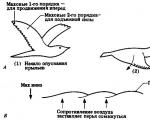
Let's consider the horizontal air flow relative to the inclined surface of the wing in the case when it...
1. Is the statement true: “Caring for offspring leads to a reduction in the birth rate in animals”? Prove your point...

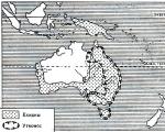
Features and habitat of the burial ground bird It’s simply amazing why it wears such a proud, beautiful...

1. Definition and origin of life script. Script theory was first developed by Eric Berne and...
General information about the use of online cash registers In accordance with Federal Law No. 290-FZ dated 07/03/2016...

History of adoption OKPDTR was adopted by the Decree of the State Standard of the Russian Federation dated December 26, No. 367) and introduced into...

The process of forming a personnel reserve in modern conditions is a very important procedure that...
In many areas of life there are such concepts as centralization and decentralization. These concepts are included...

Get acquainted with draft orders of management relating to its activities. 3.8. Sign and endorse...