Transport aspects of logistics
1.1. Factors in the development of logistics. Transport aspects of logistics Logistics is a system of promotion management sciences...
Designation:
GOST 28204-89
Name:
Basic test methods for exposure to external factors. Part 2. Tests. Ga test and manual: Linear acceleration
Valid
Date of introduction:
Cancellation date:
Replaced by:
GOST 28204-89 (IEC 68-2-7-83)
INTERSTATE STANDARD
BASIC TEST METHODS FOR THE INFLUENCE OF EXTERNAL FACTORS
Ga TEST AND GUIDE: LINEAR ACCELERATION
Official publication
Standardinform
PREFACE
1. Official decisions or agreements of the IEC on technical issues, prepared by technical committees in which all the national committees concerned are represented, express, as accurately as possible, the internationally agreed view on the issues under consideration.
3. In order to promote international harmonization, the IEC wishes that all national committees adopt this IEC standard as their national standard as far as the conditions of each country allow. Any deviation from this IEC standard should be specified as clearly as possible in the relevant national standards.
INTRODUCTION
IEC 68-2-7-83 was prepared by Subcommittee 50A, Shock and Vibration Testing, of Technical Committee IEC 50, Environmental Testing.
The standard is the second edition of IEC 68-2-7. It includes the text of the first edition (1968) and amendment No. 1 (1986), as well as minor editorial changes taking into account the test requirements given in IEC standard 68-2-47-82 “Basic test methods for exposure to external factors. Part 2. Tests. Fastening of elements, equipment and other products during dynamic testing, including impact (Ea), repeated impacts (Eb), vibration (Fc and Fd), linear acceleration (Ga) and guidance."
Drafts for the first edition of the Ga test were discussed at a meeting in 1964 in Aix-les-Bains, in 1965 in Tokyo and in 1966 in London. As a result of the decision of the last meeting, the draft, Document 50A (Central Bureau) 118, was sent to the National Committees in March 1967 for approval under the Six Month Rule.
Australia
Great Britain*
Netherlands**
Norway
Czechoslovakia
Switzerland
South African Republic of Japan
As a result of the meeting's decision, the draft, Document 50A (Central Bureau) 151, was sent to the National Committees in February 1980 for approval under the Six Month Rule.
Australia
Arab Republic of Egypt
Brazil
Great Britain*
Netherlands
New Zealand
Norway
Union of Soviet Socialist Republics
United States of America Turkey
Federal Republic of Germany
Finland
Switzerland
South African Republic of South Korea
Other IEC standards referenced in this standard:
68-1-87 Basic test methods for exposure to external factors. Part 1. General provisions and leadership.
68-2-47-82 Basic test methods for exposure to external factors. Part 2. Tests.
Fastening of components, equipment and other products during dynamic testing, including impact (Ea), repeated impacts (Eb), vibration (Fc and Fd), linear acceleration (Ga) and guidance.
721-81 Classification of external influencing factors.
* United Kingdom of Great Britain and Northern Ireland.
** In the first edition of the IEC 68-2-7 standard (1968), the national committee of the Netherlands is not included in the list of countries that voted.
UDC 621.38:620.193:006.354
Group E29
Basic environmental testing procedures. Part 2. Tests. Test Ga and Quidance: Acceleration, steady state
(IEC 68-2-7-83)
ISS 19.040 31.020
OKSTU 6000, 6100, 6200, 6300
Date of introduction 03/01/90
Checking the suitability of the design and operability of elements, equipment and other electrical products (hereinafter referred to as samples) in the presence of forces arising under the influence of linear acceleration (different from the acceleration of gravity) that take place in moving vehicles. vehicles, in particular in aircraft, rotating parts and projectiles, as well as the development of a method for testing structural strength for some elements.
Equipment, elements and other electrical products intended for installation on moving objects are exposed to forces caused by linear accelerations. Such loads are most likely to occur in aircraft and rotating machinery, although linear accelerations of significant magnitude can occur in ground vehicles.
Typically, linear accelerations occurring during operation have different values along each of the main axes of a moving object and, in addition, have different values when exposed to acceleration in the direction opposite to each axis.
If the position of the sample is not fixed relative to the moving object, the corresponding technical documentation must indicate the level of acceleration that can be applied along each axis of the sample, taking into account the maximum acceleration acting along each of the axes of the moving object.
This standard should be used in conjunction with ST IEC 68-1 (GOST 28198).
3.1.1. General provisions
Linear acceleration is created using a centrifuge, in which the acceleration is directed towards the center of the rotating system. In some special cases, the sample may be sensitive to gyroscopic effects; and the test can then be reproduced using a setup that produces linear acceleration. This requirement must be established in the relevant normative and technical documentation.
Official publication
Reproduction is prohibited
© Standards Publishing House, 1990 © Standartinform, 2006
3.1.2. Tangential acceleration
When the centrifuge rotation speed increases from zero to the value required to obtain the specified acceleration, or when the rotation speed drops to zero, the operation of the installation should be controlled so that the tangential acceleration to which the sample is subjected does not exceed 10% of the specified acceleration.
3.1.3. Acceleration gradient
The dimensions of the centrifuge relative to the sample must be such that no point of the sample (with the exception of flexible leads) is subject to acceleration, the value of which is outside the tolerances specified in and. 3.1.4.
3.1.4. Acceleration tolerances
If the linear dimensions of the sample are less than 10 cm, then the acceleration of all parts of the sample (including flexible leads) must be within + 10% of the specified linear acceleration value.
In other cases, the tolerance for the specified acceleration value should be in the range from minus 10 to plus 30%.
The sample must be secured to the test rig in accordance with the requirements of IEC 68-2-47 (GOST 28231).
Note. For safety reasons, measures must be taken to prevent the test specimen from being torn off in the event of failure of the fastening device. However, any safety devices should not affect the test.
The acceleration value should be indicated in the relevant technical documentation and, if possible, selected from the series presented in table. 1. If necessary, the angle of the acceleration vector relative to the axes of the sample must be indicated in the corresponding technical documentation (sections A1, A2, B2).
Note. The acceleration value of the test should be determined in accordance with the purpose of the test, whether it is to determine the structural strength of the specimen or whether the purpose of the test is to evaluate the ability of the specimen to withstand forces generated by a moving object or a rotating machine.
Standard test levels are:
Table 1
|
Acceleration, m ■ s 2 |
Acceleration, m ■ s 2 |
|
Note. The normalized value of the gravitational acceleration g n is defined as standard value the force of gravity of the earth, which varies with altitude and latitude. For this standard, the value of g n is rounded to the nearest whole number, i.e. to Hums-2.
The sample must be visually inspected, its dimensions determined and its functioning checked in accordance with the requirements of the relevant technical documentation.
6.1. Acceleration, unless specifically stated in the relevant technical documentation, should act alternately in both directions of three mutually perpendicular axes, which are the three main axes of the sample.
6.2. The centrifuge must rotate at the speed necessary to obtain a given level of acceleration.
6.3. The required rotation speed must be maintained for a time of at least 10 s or for the time specified in the relevant technical documentation.
6.4. The relevant technical documentation must indicate the appropriate acceleration levels (Section A2) and which of the following operating conditions or condition of the sample must be met:
1) the sample must be in working condition and the characteristics of the sample must be within the limits specified in the relevant technical documentation;
2) the sample must be in working condition, but the characteristics of the sample do not necessarily have to be within the values specified in the relevant technical documentation. In this case, the sample should not experience any irreversible changes in parameters;
3) the sample should not have irreversible changes in parameters, although it may be inoperative:
4) the sample should not be torn from the fastenings, although it may be mechanically damaged and have irreversible changes in parameters.
6.5. The relevant regulatory documentation must indicate the order in which the checks specified in i. are carried out. 6.4 and sec. A2 of Appendix A.
The sample must be visually inspected, its dimensions determined and its functioning checked in accordance with the requirements of the relevant technical documentation.
If linear acceleration testing is included in the relevant technical specification, the following data must be provided as required:
Section or paragraph number
a) type of test equipment...................................3.1
b) and c) method of fastening the samples.................................3.2
d) acceleration levels (sections A2 and B2)....................................4
e) axis and direction of acceleration (Section A1)..................4.6
f) initial measurements........................5
g) exposure time...................................6.3
h) operating conditions or condition of the sample (Section B1)........6.4
j) check procedure.............................6.5
k) final measurements........................7
MANAGEMENT
A.1. Test sample orientation
In many applications, especially in aviation, the forces that cause an increase in the acceleration of a moving object are always unpredictably complex, but can be considered at any time as a single force, defined by the direction of its angular position relative to the three axes of the moving object. For the calculation, the maximum acceleration levels corresponding to a specific displacement of a moving object are decomposed into components or components and determined relative to each of the main axes of the moving object.
If the position of the sample is known with respect to a moving object, and if it is necessary to reproduce three components of acceleration simultaneously, then these three components can be summed and the sample is subjected to a simple acceleration equal in amplitude and direction to the resulting levels of the three components. However, this requires rather complex mounting arrangements, which are necessary to orient the sample relative to the test setup so that the acceleration is directed along the resultant line. If there is no need to maintain the ratio of the angles between the resulting acceleration and the samples, then it is simpler and more equivalent to apply along the main axis of the sample the resulting acceleration, which is the largest of the three given component levels. Appropriate levels of acceleration components must be applied along the remaining axes.
If the position of the specimen in relation to the moving object is unknown, then the maximum resulting level for an individual moving object must be applied alternately along each of the three principal axes of the specimen.
A.2. Acceleration levels for testing
Some of the acceleration values listed in Sect. 4 represent accelerations under real-world conditions, others (especially higher acceleration levels) are presented under simulated conditions used to test some electronic components for structural strength. Given the large acceleration values that can occur in a rotating machine, actual acceleration levels for some purposes may be the same as simulated levels for other purposes.
Assessing the design quality of aircraft equipment requires that it be tested alternately for stability and strength at various levels of acceleration. The requirements for the stability and strength of equipment are related to each other by a certain coefficient, which is established in accordance with the requirements for the design of aircraft equipment. Typically the following four conditions must be met:
1) test or operational level - the level at which the sample must function; its characteristics must be within the required limits;
2) an additional, higher level may be specified at which the sample must function, while the characteristics of the sample may be outside the specified limits;
3) structural or limit level - a higher acceleration level to test resistance to deformation;
4) in addition, the linear acceleration test can be used as a means of testing the ability of the sample to be firmly fixed and not to be torn from the fastenings in emergency situations, creating an emergency situation for personnel either directly or by closing an emergency exit, etc.
The relevant technical documentation should indicate which of these conditions must meet the test requirements, which acceleration levels and operating conditions of the sample (p. 6.4 and 6.5) must be used during testing.
In some application conditions, the developer of the corresponding scientific and technical documentation cannot always recommend the level of impact acceleration corresponding to listings 1-4, but instead it is sufficient to indicate only one level, which is determined by the maximum measured or calculated level of acceleration of a given moving object and the established safety margin. If required, the required operating mode is established in the relevant technical documentation (see paragraphs 6.4 and 6.5).
When choosing the degree of acceleration severity in the corresponding technical documentation, one should take into account the fact that in a given direction the maximum acceleration at different points of a moving object can differ significantly.
Some elements, namely semiconductor products, are tested for structural strength (internal mechanical components) at very high high levels acting acceleration. Although the applied acceleration has nothing to do with actual operating conditions, these tests are used as a simple way to obtain a large acceleration value to detect possible design defects.
When testing components or apparatus containing rotating parts, such as gyroscopes, in the case of a centrifuge, difficulties arise due to the interaction between the rotation of the part and the rotation of the centrifuge. In this case, the relevant technical documentation should indicate the corresponding test method, operating conditions and permissible changes in operating tolerances during the interaction of acceleration during the holding process.
ADDITIONAL GUIDE B1. Target
The purpose of the linear acceleration test is to simulate in components and equipment the loads caused by linear accelerations similar to those experienced when installed on rotating parts, projectiles, moving vehicles and, in particular, spacecraft.
This test can also be used to evaluate the quality of the design and manufacture of members in relation to their structural strength.
The relevant technical documentation must specify whether the samples must function during testing or simply withstand the test conditions. In any case, the relevant technical documentation must indicate the permissible value of tolerances for the characteristics of the sample and/or the permissible degree of violation of the characteristics in accordance with and. 6.4, by which one can judge whether the sample meets the requirements.
AT 2. Selection of degrees of hardness (see sections 4, 6 and 8(1 and 8g)
Acceleration levels during testing - according to Appendix A, section. A2.
The developer of the corresponding technical documentation for this test must take into account Section. 8 to ensure that all information in this paragraph is included in the relevant technical documentation.
Where possible, the degree of test severity imposed on the sample should be determined by the expected conditions to which the sample is subjected, both during transport and during use. If such information is available, the appropriate degree of hardness must be selected from the values given in Section. 4.
When external influencing factors are unknown, the most suitable degree of severity should be selected from the table. 1, which indicates the degrees of rigidity most suitable for samples for various areas of their application.
Note. Attention should be paid to the IEC 721* standard, given the fact that various sections of this standard consider the levels of applied linear acceleration that occur in real conditions. The purpose of this standard is to standardize acceleration values specified for testing that produce the same effect as accelerations under real-world conditions.
table 2
Examples of test severity levels typical for various applications
Note. This table is not mandatory and only lists the hardness levels that are typical for various applications. It must be borne in mind that under operating conditions, actual degrees of rigidity may differ from those indicated in the table. 2.
VZ. Requirements for tolerances (see paragraphs 3.1.2 and 3.1.4)
This test method is a highly reproducible test when the linear dimensions of the sample are small, for example, not exceeding 10 cm. For large samples, the reproducibility of the test is of a lower order and depends on the relative sizes of the sample and the centrifuge.
The development of a state standard is not envisaged.
INFORMATION DATA
1. By Decree of the USSR State Committee on Standards dated August 15, 1989 No. 2555 put into effect state standard USSR GOST 28204-89, in which the standard of the International Electrotechnical Commission IEC 68-2-7-83 with Amendment No. 1 (1986) is directly applied, from 03/01/90
2. Reference regulatory and technical documents:
3. Notes on the implementation of GOST 28204-89
Technical content of the IEC 68-2-7-83 standard “Basic test methods for exposure to external factors. Part 2. Tests. Ga test and manual: Linear acceleration" are accepted for use and extended to consumer electronics products
4. REPUBLICATION. August 2006
Typed into FSUE "Standardinform" on a PC
Printed in the branch of FSUE "Standardinform" - type. “Moscow Printer”, 105062 Moscow, Lyalin lane, 6
7.3.1. Test conditions and test equipment used
The impact of linear accelerations on various products during laboratory tests is ensured using special centrifuges that create radially directed accelerations in the horizontal plane. Depending on the test mode, as well as the overall dimensions and weight of the products being tested, various centrifuges are used, which are included in the design of the corresponding installations. It should be borne in mind that the block diagrams of the installation may vary depending on the choice of drive, the design of the automatic control system, the converter used, etc.
Block diagram shown in Fig. 7.18, reflects the general principle of constructing linear acceleration installations. The main unit of the centrifuge is drive 1, which together with gearbox 2 determines a number of installation parameter values. The resulting rotational motion is transferred to the table (platform) 4 of the centrifuge, on which the test product is mounted. To test the stability of a product that is under load, a current collector device 5 is used. Linear accelerations are controlled
are measured using a measuring instrument 6, consisting of a transducer 3 and measuring instrument 7. Signals from the measuring device can be supplied via a feedback circuit to the automatic control system 8, which maintains the constancy of the specified test modes by influencing the control signals on the power source 9.
Centrifuges can be classified according to the following criteria:
As intended - for testing linear overloads and the combined effects of environmental factors;
By type of drive - with electric drive and with hydraulic drive;
According to the developed linear acceleration: A - up to 200, B - up to 500, C - up to 1000, D - 2000, D - over 2000 m/s2;
By design - open and chamber type, with a fixed and rotary table;
In terms of carrying capacity, small - up to 10 kg, medium - up to 50 kg, heavy - up to 100 kg and super-heavy - over 100 kg.
The main parameters characterizing centrifuges are the following:
1. Maximum linear acceleration.
2. Range of linear accelerations at a given radius of rotation (Table 7.6).
Measurements are made by various methods: ultrasonic, radiographic, eddy current.
GOST 30630.0.0-99 Test methods for resistance to external influences of machines, instruments and other technical products. General requirements
GOST R 51805-2001 Test methods for resistance to mechanical external influences of machines, instruments and other technical products. Linear Acceleration Tests
GOST 28204-89 Basic test methods for exposure to external factors. Part 2. Tests. Ga Tests and Manual: Linear Acceleration
Centrifuge C 1/150:
OKP code : 42 7190 – Instruments and automation equipment for general industrial use. Machines and instruments for measuring mechanical quantities. Machines and instruments for determining the mechanical properties of materials. Accessories, devices and components for machines and devices for/mechanical determination. Metal testing.
OKP code : 42 7354 Machines and instruments for measuring mechanical quantities. Devices for measuring deformation. Strain gauges.
HS Code : 8 421 19 200 0 – centrifuges used in laboratories.
For different products, the shape of the curve of the temporary value of the change in overload is different. Overload laws differ in amplitude, rise time and other characteristics.
Of particular interest to developers of units and hardware components are overloads caused by dynamic factors.
A distinctive feature of overloads is the relatively long duration of action, usually measured from 1 s to several tens of seconds. However, the shapes of the pulses are varied, which is of significant importance when choosing a method for simulating them.
A feature of group I overloads is the rapid front of the rise and fall of the overload. Therefore, simulating the laws of changing the overloads of this group in centrifuges presents a number of difficulties.
Overloads of group II have the form of a “bell-shaped” pulse; the rise time of the overload and the duration of the entire process are usually measured in tens of seconds. Maximum overload values reach several hundred seconds.
It is impossible to reproduce real Group II overload curves on conventional centrifuges, since existing installations are designed to test products at a constant angular velocity of the centrifuge.
The specific features of overload curves (long rise time and insignificant maximum amplitude) make it possible to recommend for their reproduction a centrifuge with an angular velocity controlled according to a certain law, i.e. a program centrifuge.
Centrifuges can be classified according to the following criteria:
By purpose - for testing for linear overloads (with an overload rising edge of 0.001 - 0.1 s; with an overload rising edge of more than 0.1 s), for testing for the combined influence of environmental factors;
By drive type - with electric drive, with hydraulic
drive, with combined drive;
According to the developed linear acceleration, the following categories are conventionally distinguished: “A” - up to 250 m/s 2 , “B” - up to 500 m/s 2 , “B” - up to 1000 m/s 2 , “D” - up to 2000 m/s s 2, “D” - over 2000 m/s 2;
By design - open and chamber type, with fixed and
rotary table, with impact platforms: centrifuges with rotary tables are used mainly to simulate the ascending linear section of the sinusoidal burst of group I overload curves; centrifuges with rotary and fixed tables may have a variable radius of rotation of the product;
By load capacity - small (up to 10 kg), medium (up to 50 kg), heavy
light (up to 100 kg) and super-heavy (over 100 kg).
The main parameters characterizing centrifuges are
the following:
1) maximum linear acceleration;
2) range of linear accelerations at a given radius of rotation;
3) deviation of linear acceleration from the specified value. If the linear dimensions of the product are less than 10 cm, it should not exceed 10%. In other cases, acceleration should be within -10%...+30%
set value;
4) duration (or duration) of exposure to linear
accelerations during testing. Most critical during testing
action during the acceleration increase, so the duration itself
impact with a given linear acceleration may be small.
5) duration of acceleration (increase ) τ n, and braking (decline) τ With;
load front must satisfy the condition
n= ≥ 100 H Cτ τ ,
where n is the centrifuge rotation speed, min -1.
Block diagram of linear acceleration installation: 1-drive, 2-gearbox, 3-measurement of speed, 4-centrifuge table, 5-current collector, 6-measurement of parameters of tested products, 7-measuring device, 8-automatic control system, 9-power supply.
The block diagram reflects the general principle of constructing linear acceleration installations. The main unit of the centrifuge is drive 1, which together with gearbox 2 determines a number of installation parameter values. The resulting rotational motion is transferred to the centrifuge table 4, which provides fastening of the tested products. To test products for stability, when the product is under load and its parameters are monitored using a measuring instrument 6, a current collector device 5 is used. Linear accelerations are controlled using a measuring instrument consisting of a transducer 3 and a measuring device 7. Signals from the measuring device can be supplied via a feedback circuit to the automatic control system 8, which maintains the constancy of the specified test modes by influencing control signals on the power source 9.
Let's look at the basic designs of centrifuges used. The simplest setup for reproducing linear accelerations has open type centrifuge. In addition to the centrifuge, the installation kit also includes rack 1 with control units. Table (platform) 3 The centrifuge is driven by an electric motor 6 through a gearbox 5. The centrifuge table has threaded holes 4, providing fastening of products or devices.

Tables must have high mechanical strength and rigidity to prevent vibration. To reduce aerodynamic drag, the table plane must be horizontal. To ensure testing of products in working condition under electrical load A current collecting device is provided, the design of which includes a collector 2 with current leads ending in plug blocks. Centrifuges must have provisions for static and dynamic balancing.
To simulate the ascending section and sinusoidal burst of group I overload curves, centrifuges with rotary tables are used.
The laws of overload can be simulated on a special centrifuge, consisting of two inertial bodies: flywheel 1 and traverse 2. The flywheel and traverse have a common vertical axis of rotation. The flywheel is equipped with retractable stops 5, flat springs 6 are mounted on the traverse. The test product 4 is installed on the traverse 2. The flywheel accelerates to a certain speed ω 0, after which the stops rise from it. The latter come into contact with flat springs and push the traverse into rotation. As soon as the angular velocity of the traverse exceeds the angular velocity of the flywheel, the flywheel is disengaged from it.
The rotation of platform 3 is associated with the acceleration of the traverse so that the axis of the product follows the resultant of two accelerations: tangential ω to and centripetal ω c.
All parameters of the centrifuge are calculated in such a way as to ensure the specified overload law.
GOST R 51805-2001
Group T51
STATE STANDARD OF THE RUSSIAN FEDERATION
TEST METHODS FOR RESISTANCE TO MECHANICAL EXTERNAL INFLUENCED FACTORS OF MACHINES, DEVICES AND OTHER TECHNICAL PRODUCTS
Linear Acceleration Tests
Mechanical environment stability test methods for machines, instruments and other industrial products. Tests for influences of acceleration steady state
OKS 19.060
OKP 34 2000
Date of introduction
for newly developed and modernized products 2002-07-01
for manufactured products 2004-07-01
Preface
1 DEVELOPED AND INTRODUCED by the Technical Committee for Standardization TC 341 “External influences”
2 ADOPTED AND ENTERED INTO EFFECT by Resolution of the State Standard of Russia dated August 29, 2001 N 361-st
3 This standard complies international standard IEC 60068-2-7-83, first edition "Basic environmental test methods - Part 2: Ga tests and guidance - Chapter 7: Linear acceleration" with additional requirements reflecting the needs of the country's economy
4 INTRODUCED FOR THE FIRST TIME
Introduction
This standard is part of the set of standards "Test methods for resistance to external influences of machines, devices and other technical products" (group of standards GOST 30630) given in GOST 30630.0.0-99, Appendix E.
This standard conforms to the international standard IEC 60068-2-7-83. At the same time, the standard complements and clarifies test methods, their classification and composition, linking test methods (modes) with operating conditions of products, and covers the entire range of technical products, which is absent in international standards for external influencing factors.
In connection with the above, it is currently impossible to fully use international standards on external influences as interstate standards.
This standard applies to machines, instruments and other technical products of all types (hereinafter referred to as products) and establishes a method for testing them for the effects of linear acceleration (test 107), including to verify compliance with the technical requirements specified in the standards and technical conditions for products, as well as GOST 30631.
The standard should be used in conjunction with GOST 30630.0.0.
The requirements of sections 4 and 5 of this standard are mandatory as they relate to safety requirements.
The procedure for putting the standard into effect is given in Appendix A.
This standard uses references to the following standards:
GOST 15150-69 Machines, instruments and other technical products. Versions for different climatic regions. Categories, operating, storage and transportation conditions regarding the impact of environmental climatic factors
GOST 26883-86 External influencing factors. Terms and Definitions
GOST 30630.0.0-99 Test methods for resistance to external influences of machines, instruments and other technical products. General requirements
GOST 30631-99 General requirements for machines, instruments and other technical products in terms of resistance to mechanical external influences during operation
This standard uses terms with appropriate definitions related to the following areas:
- general concepts external influencing factors (hereinafter referred to as EAF) - according to GOST 15150 ;
- requirements for products for mechanical VVF - according to GOST 30631 ;
- tests for resistance to WWF - according to GOST 30630.0.0.
4.1 Tests are carried out to check the ability of products to withstand the destructive action and (or) perform their functions under the influence of linear acceleration corresponding to the operational one.
Tests are also carried out during the manufacturing process of the product in order to determine the specified strength of its structure.
Tests are carried out according to 107-1.
Note - Previously released regulatory documentation Instead of the phrase “structural strength,” the phrase “structural strength” was used.
4.2 The testing facility (centrifuge) must ensure that linear (centripetal) acceleration is obtained, the value of which corresponds to that specified in the standards or technical specifications (hereinafter referred to as standards and specifications) for the product.
It is allowed to use a different type of installation for testing products sensitive to the gyroscopic effect, if this is established in the standards and specifications for these products.
4.3 Tests are carried out taking into account the requirements of sections 4-6 GOST 30630.0.0.
4.4 Fastening of products is carried out in accordance with the requirements of section 5 GOST 30630.0.0.
Fastening of products when checking the strength of their structure during the production process is carried out by the housing, taking measures to protect the housing and external terminals from destruction.
If the products have flanges, it is recommended to fasten them to the flange when checking the strength of the structure.
4.5 Visual inspection products and measurements of their parameters are carried out in accordance with the requirements of section 4 GOST 30630.0.0.
4.6 Products are placed on a centrifuge table or device intended for installation of products in such a way that the deviation of the acceleration values at any point of the product (including flexible leads) relative to its center of mass or geometric center of rotation does not exceed plus 10% of the acceleration value at the control point for products with the largest overall dimensions of less than 100 mm and from minus 10% to plus 30% for products with the largest overall dimensions of 100 mm and more.
If the acceleration exceeds 5000 m s (500 g), then a deviation of the acceleration values at any point of the product is allowed from minus 10% to plus 30%, regardless of overall dimensions.
4.7 The control point, relative to which the radius of the product’s rotation axis is calculated, is selected in the center of the centrifuge table or other device intended for fastening products (the position of the control point is determined by the design of the centrifuge).
4.8 Tests are carried out by exposing products to linear acceleration, the value of which must comply with the technical requirements established in the standards and specifications for products, taking into account the conditions of their operation and (or) transportation, as well as in the specifications for products or test programs (TP) during testing structural strength of products during the production process.
4.9 The acceleration or deceleration time of the centrifuge in seconds must satisfy the condition
where is the value of linear acceleration, m s;
- distance from the center of the centrifuge rotation axis to the control point, m;
-
centrifuge platform rotation speed, min.
It is allowed to set the acceleration or deceleration time in such a way that the tangential acceleration value does not exceed 10% of the linear acceleration value during testing.
4.10 Test duration - 3 minutes in each direction for acceleration values up to 5000 m s (500 ) and 1 min for values above 5000 m s (500 ) unless more time is required for monitoring and (or) measuring product parameters, or no longer time is set in technical requirements, standards and specifications for products according to the conditions of their use.
4.11 During testing, unless otherwise specified in the standards and specifications for products or PI, product parameters are monitored. The list of tested parameters, their values and verification methods are indicated in the standards, product specifications and PI.
It is recommended to select a list of parameters, by changing which during testing one can make a conclusion about the resistance to the effects of linear acceleration of the product as a whole.
4.12 Selection of directions in which the product is affected by linear acceleration - according to 5.3 GOST 30630.0.0.
In this case, for each selected direction of impact, the product is tested in two opposite positions.
4.13 Test results should be assessed according to 4.21 GOST 30630.0.0.
During testing, measures must be taken to prevent the test sample from being torn off if the fastening device breaks.
In this case, any safety devices should not affect the test results.
APPENDIX A
(required)
A.1 For newly developed standards and products (as well as modernized products), the date of introduction of the standard is set to July 1, 2002.
A.2 For standards and products developed before 2002, the introduction of the standard is carried out in the period until 2004 when the standards and specifications for products are revised.
At the same time, for products developed before July 1, 2002, when conducting the first tests after July 1, 2002 to confirm the requirements for resistance to airborne explosives, as well as periodic tests of products in production, it is recommended to be guided by the requirements of this standard.
APPENDIX B
(informative)
B.1 Data on the compliance of the test method with this IEC 60068-2-7-83 standard are given in Table B.1.
Table B.1
This standard | IEC 60068-2-7-83 | Degree of compliance |
||
Test method | Method number | Test method | Method designation | |
Linear Acceleration Test (Test 107) | Ga Test and Guide: Linear Acceleration | The test method of this standard is in accordance with IEC 60068-2-7-83. The shortest test duration specified in this standard exceeds that given in IEC 60068-2-7-83. |
||
B.2 Reference data on the ranges of linear acceleration values used (according to IEC 60068-2-7-83) when testing certain types of products are given in Table B.2.
Table B.2
Acceleration, m s | Application example |
30<<100 | Normal level of testing for aircraft products |
50<< 200 | a) Limit level of testing of products intended for aircraft. |
b) To test the structural strength of products with the exception of the 1000 range<<
5000 |
|
Normal level of testing of products intended for space technology |
|
Test to verify structural strength during the production of semiconductor devices, integrated circuits, and other similar products |
The text of the document is verified according to:
official publication
M.: IPK Standards Publishing House, 2001

1.1. Factors in the development of logistics. Transport aspects of logistics Logistics is a system of promotion management sciences...

NUCLEAR energy (nuclear energy) is a branch of energy that uses nuclear energy for electrification and...

CONFERENCE OF RESEARCH AND PRACTICAL WORK “DISCOVERY” Topic: “Birth of a clay toy” Section “Technology”...

Beginning The invention of photography If you think that photography was created by one person, then you are deeply mistaken And if you...

Modern society presents the legal profession as extremely prestigious and well-paid. Hollywood movies...
Controlling is a special concept of enterprise management, which is based on comprehensive information...

How to draw up a letter of consent correctly? Is it necessary to repeat the contents of the request letter, what to title...

According to the rating, Novye Izvestia, Izvestia and Rossiyskaya Gazeta took third, second and first...

Previously, notification of the opening of an account was included in the mandatory category. Since May 2014, such an obligation...
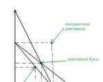
Forms of competition in the market In most countries of the world there has been a transition to a market model of economic...

Agriculture is a rather difficult industry for beginners: there is investment and...

Features of EDMS "Practice" Easy maintenance and implementation Intuitive interface Possibility...

Oleg Sergeevich Abramkin, head of the scientific and educational department, talks about the Olympiad for schoolchildren “Russia...

4249 01/11/2011 The phrase “human dignity” is heard very often from the lips of everyone involved...

NUCLEAR energy (nuclear energy) is a branch of energy that uses nuclear energy for electrification and...

CONFERENCE OF RESEARCH AND PRACTICAL WORK “DISCOVERY” Topic: “Birth of a clay toy”...