What are the job responsibilities of a health and safety engineer in a management organization?
The person responsible for occupational safety and health (OHS) at work is a person specially trained for this purpose – an HSE engineer. He...
DLP (Digital Light Processing) technology is used in the production of DLP projectors. This technology is the most common today and is a competitor to 3LCD. This technology is based on a device made of multiple micromirrors - DMD (Digital Micromirror Device). Under electronic control, the mirrors can change their angle, focusing light onto the screen. To obtain the black areas of the image, the micromirrors bend and direct the light into the light absorber; in other cases, the light is directed into the focusing lenses. Each pixel on the screen is a reflection of light from one micromirror. To color the light, it is passed through light filters.
DLP technology
Different manufacturers have different ways of coloring the light in DLP projectors. The most commonly used technology is the color wheel, which consists of three color sectors. The light passes through the colored segment, acquiring a certain color, then is reflected from the mirrors and hits the screen. The color wheel rotates, coloring the light beam into a different shade, and micromirrors direct it to the projection screen. So, during the rotation process, the colors replace each other, and accordingly, the images on the screen change - red, green, blue. Since the wheel rotates at a very high speed and the picture changes also very quickly, a person does not see the change of pictures, but perceives a complete color image. Viewing such a DLP projector for a long time may tire some particularly sensitive people. Also, in such DLP projectors, the so-called rainbow effect is possible - multi-colored rays appear at the edges of the image, which is distracting and interferes with watching a movie, etc. The faster the picture of different colors changes, the less noticeable the rainbow effect. To eliminate these shortcomings, manufacturers increase the number of segments in the color wheel. The contrast of the picture when using DLP technology is better than 3LCD, because the mirrors completely reflect the light into the light absorber, when displaying black areas, the image looks really black. High contrast is one of the main advantages of DLP projectors, but in order to minimize the disadvantages of the technology - eye fatigue and the rainbow effect, manufacturers have to use expensive techniques, which affects the final price of a good DLP device.
There are also other options for coloring light, similar to 3LCD - three color filters and three DMD devices, each of which, independently of each other, reflects light only of its own shade. As a result, there is no change of pictures, and the output is a finished color image. Thus, this solution does not have the disadvantages described above; it is very comfortable to look at such a picture. These 3DLP projectors are some of the best on the market, but they are also quite expensive.
The article provides an analysis of those used in procurement, in particular foundry production. computer technology, allowing you to dramatically reduce the time it takes to launch new products. These technologies are of particular importance in the manufacture of foundry models, molds and equipment.
When developing and creating new industrial products, the speed of passing through the R&D stages is of particular importance, which, in turn, significantly depends on technological capabilities pilot production.
In particular, this concerns the production of casting parts, which are often the most labor-intensive and expensive part common project. When creating new products, especially stage of development work in pilot production, which is characterized by variant studies, the need for frequent design changes and, as a consequence, constant correction of technological equipment for manufacturing prototypes, the problem of quickly producing casting parts becomes key.
In pilot production, traditional methods of manufacturing foundry equipment manually or using machining remain predominant. This is due to the fact that at the R&D stage, when the design of the product has not yet been worked out, it is inappropriate to create equipment for mass production to produce samples. Under these conditions, foundry equipment is a very expensive product; it turns out to be, in fact, a one-time product, which is not used in further work on the product due to changes in the design of the product during development work. Therefore, each approach of the part design to the final version often requires new equipment, and therefore traditional methods are not only expensive, but also time-consuming.
The transition to digital description of products - CAD, and the additive technologies that subsequently appeared, made a real revolution in foundry production, which was especially evident in high-tech industries - aviation, aerospace, nuclear, medicine and instrument making - those industries characterized by low-volume, often piece-by-piece production. It is here that the departure from traditional technologies and the use of new methods for producing foundry synthesis molds and synthesis models using layer-by-layer synthesis technologies have radically reduced the time for creating new products. For the production of the first prototype of the cylinder block
(Fig. 1) traditional methods require ≥ 6 months, and most of the time is spent on creating equipment.
Using Quick-Cast technology for this purpose (growing a casting model from a photopolymer on an SLA machine followed by casting using a gasified model) reduces the time required to obtain the first casting from six months to two weeks!
Fig.1 Quickcast model (a) and casting cylinder block (b)
The same part can be produced by a less accurate, but quite suitable technology - casting into grown sand molds, when there is no need to make a casting model at all: the “negative” of the part is grown - the mold. A mold for casting such a large part as a cylinder block is grown in fragments, then assembled in a flask and poured. The whole process takes several days. A significant portion of “regular” castings, which do not have special requirements for accuracy or internal structure, can be obtained as finished products within a few days:
Total: 3...4 days (each stage – one day), taking into account the preparatory and final time. Almost all automobile and aircraft manufacturing companies in industrialized countries have dozens of AF machines serving R&D in their pilot production arsenal. Moreover, these machines are beginning to be used as “ordinary” technological
equipment in a single technological chain and for mass production.
Additive technologies (AT) and rapid prototyping Additive Fabrication (AF) or Additive Manufacturing (AM) are terms accepted in English technical vocabulary that denote an additive, that is, “adding,” method of producing a product, as opposed to traditional methods of machining by “subtraction” ( subtractive) material from a solid workpiece. They are used along with the phrase Rapid Prototyping (or RP technologies) - rapid prototyping, but have a more general meaning that more accurately reflects the current situation. We can say that RP technology, in the modern sense, is part of AF technologies, “responsible” for the actual prototyping using layer-by-layer synthesis methods. AF or AM technologies cover all areas of product synthesis, be it a prototype, prototype or serial product.
The essence of AF technologies, like RP technologies, is the layer-by-layer construction of products - models, molds, master models, etc. by fixing layers of model material and their serial connection with each other in different ways: sintering, fusion, gluing, polymerization - depending on the nuances of a particular technology.
The ideology of additive processes is based on technologies that are based on a digital description of the product, its computer model, or the so-called. CAD model. When using AF technologies, all stages of project implementation - from idea to materialization (in any form - intermediate or finished product) are in a “friendly” technological environment, in a single technological chain, where each technological operation also performed in a digital CAD\CAM\CAE system. In practice, this means a real transition to “paperless” technologies, when, in principle, traditional paper drawing documentation is not required to manufacture a part.
Although there are various AF systems on the market for producing models using different technologies and from different materials, what they have in common is the layer-by-layer principle of constructing the model. ATs play a special role in the modernization of foundry production, allowing them to solve previously unsolvable problems and “grow” foundry models and molds that cannot be produced using traditional methods. The production time for model equipment has been radically reduced. The development of vacuum film technologies based on the forms and models obtained by AT has made it possible to reduce the production time of prototypes, and, in some cases, serial products by several times and tens of times. Recent advances in the field of powder metallurgy have made it possible to significantly expand the capabilities of AT to directly “grow” functional parts from metals and obtain new structural materials with unique properties(spray forming technologies, etc.).
Modern AT Centers often contain the words design and technology in their full name, thereby emphasizing the unity, and not the struggle of contradictions, between the designer and the technologist. Taking into account the specifics of Russian industry, where the production of a huge range of products from different materials is often concentrated within one enterprise, where many enterprises are forced to maintain their “ subsistence farming", this is a rational approach. Experimental foundries in the technologies for producing both metal and plastic products have much in common, and with the use of AT they are even closer in the equipment used, and in technological methods, and in the education and training of professional personnel.
As already noted, AT is of particular importance for the accelerated production of casting parts, in particular, for obtaining:
Casting models can be obtained (grown) from the following materials:
 Rice. 2. SLS machine SinterStation Pro and turbine wheel model
Synthesis models from polystyrene powder. Polystyrene is widely used as a model material for traditional wood products. However, due to the rapid development of layer-by-layer synthesis technologies, it has gained particular popularity for prototyping, as well as for the industrial production of piece and small-scale products. Polystyrene models are produced on AF machines using SLS technology - Selective Laser Sintering - layer-by-layer sintering powder materials(Fig. 2). This technology is often used when it is necessary to quickly make one or more castings of complex shapes of relatively large dimensions with moderate accuracy requirements.
The model material - polystyrene powder with a particle size of 50...150 microns is rolled with a special roller onto a working platform installed in a sealed chamber with an atmosphere of inert gas (nitrogen). The laser beam “runs” where the computer “sees” the “body” in a given section of the CAD model, as if shading the cross-section of the part, as a designer does with a pencil on a drawing. Under the influence of the heat of the laser beam, the polystyrene particles are sintered (~ 120°C). Then the platform is lowered by 0.1...0.2 mm, and a new portion of powder is rolled onto the cured layer, a new one is formed, which is also sintered with the previous one.
The process is repeated until the model is completely built, which at the end of the process is enclosed in an array of unsintered powder. The model is removed from the machine and cleaned of powder. The advantage of the technology is the absence of supports, since the model and all its layers under construction are constantly supported by an array of powder.
The machines available on the market from 3D Systems and EOS make it possible to build fairly large models - up to 550x550x750 mm (which is important, since large models can be built as a whole, without gluing individual fragments, which increases the accuracy and density of the casting). Very high level of detail in model construction: surface elements (part numbers, symbols, etc.) can be constructed with fragment thicknesses up to 0.6 mm, guaranteed model wall thickness up to 1.5 mm.
 Rice. 3. Polystyrene model after growth (a) and infiltration (b) and cast iron (c)
 Rice. 4. Polystyrene models (a) and castings from
Al-alloy (b)
Fundamentally, casting technologies for wax and polystyrene models do not differ (Figures 3 and 4). The same molding materials, the same foundry and auxiliary equipment are used. Is it possible that the wax model is “lost wax”, and the polystyrene model is “burnt out”.
But working with polystyrene models requires attention when burning: a lot of gases are released that require neutralization, the material partially burns out in the mold itself, there is a danger of ash formation and clogging of the mold, it is necessary to provide for the possibility of material draining from stagnant zones, calcining furnaces with programmers must be used, and , the programs for burning polystyrene and melting wax are significantly different. But in general, with a certain amount of skill and experience, LGM gives a very good result.
Disadvantages of technology
The process of powder sintering is a thermal process with all its inherent disadvantages: uneven heat distribution throughout the working chamber, throughout the mass of material, warping due to temperature deformations.
Polystyrene powder is not fused, like polyamide or metal powders, for example, but is sintered - the porous structure of the model is similar to the structure of foam plastic. This is done specifically to facilitate the subsequent removal of the model material from the mold with minimal internal stress when heated.
The constructed model, unlike, for example, a wax model, requires careful handling both during cleaning and during further preparation for molding.
To give strength and ease of work with it (joints with the gating system, molding), the model is impregnated with a special wax composition at ~ 80°C - a process called infiltration. (Fig. 3 shows infiltrated red models, while white polystyrene models are removed from the machine). This also carries the risk of deforming the model and requires certain personnel skills.
Recently, polystyrene powders have appeared that do not require infiltration. This alleviates but does not eliminate the problem. In addition, infiltration in the form of wax is not always a harmful necessity. It melts in the flask during burning before polystyrene, and when the latter becomes fluid, it promotes its removal from the mold, thereby reducing the mass of the “burned out” part of the polystyrene and reducing the likelihood of ash formation.
 Rice. 5. SLS model of camshaft and sand molding box
Thus, when we talk about moderate requirements for accuracy when using SLS technology, we mean the noted reasons why the accuracy of products obtained by SLS technology cannot be higher than when using other technologies not related to temperature deformations , such as photopolymerization technologies (Fig. 5).
Speaking about SLS technology, we note one more, not related to polystyrene, but “related” direction, sometimes used in foundry production. This is growing equipment from powdered polyamide. Polyamide is widely used for functional prototyping; durable polyamide models in many cases allow you to reproduce a prototype as close as possible to the finished product.
In some cases, it is advisable to use polyamide models as an alternative to wooden ones. The model is grown in the same way as the polystyrene one. At the same time, if possible, make it hollow with the minimum possible wall thickness. Then the model, to give it strength and rigidity, is filled with epoxy resin, after which it is fixed in a flask, painted and then traditional molding technology is used. An example of such “fast” technological equipment for molding an internal combustion engine camshaft is shown in Fig. 5. Due to its large length, the model is made of two parts, the parts are glued together, filled with epoxy resin and fixed in a flask; Duration of operations is two days.
Synthesis models from photopolymers. The essence of the technology is the use of special photosensitive resins, which are cured selectively and layer by layer at points or places where a beam of light is supplied according to a given program. There are different methods of illuminating the layer (laser, ultraviolet lamp, visible light). There are two main technologies for creating models from photopolymer compositions: laser stereolithography or SLA technology (Steriolithography Laser Apparatus), or stereolithography - curing the layer with a laser, and “instant” illumination of the layer - curing the photopolymer layer with a flash of an ultraviolet lamp or spotlight.
The first method involves sequentially “running” a laser beam over the entire surface of the layer being formed where the “body” of the model is in the cross-section. According to the 2nd method, curing of the entire layer occurs immediately after or during its formation due to radiation from a controlled light source - visible or ultraviolet.
The difference in the methods of forming layers also determines the difference in the speed of building the model. Obviously, the growing speed of the 2nd method is higher. However, stereolithography has been and remains the most accurate technology and is used where the requirements for surface cleanliness and accuracy of model construction are basic and decisive.
However, “illumination” technologies with a given exposure, used, for example, by Objet Geometry and Envisiontec, in many cases successfully compete with stereolithography, reserving a clear advantage in the speed of construction and cost of models. A number of production tasks can be equally successfully solved using AF machines of different levels.
Thus, optimal choice technology for obtaining models and, consequently, prototyping equipment is often not obvious and must be carried out taking into account specific production conditions and real requirements for models. In cases where the variety of tasks being solved is obvious, it is advisable to have two machines: for the manufacture of products with increased requirements and for performing “routine” tasks and replicating models.
Laser stereolithography. 3D Systems is a pioneer in the practical development of rapid prototyping technologies. In 1986, it first introduced for commercial development the SLA-250 stereolithography machine with a construction zone size of 250×250×250 mm. The basis of the SLA process is an ultraviolet laser (solid-state or CO2), where the laser beam is not a source of heat, as in SLS technology, but of light. The beam “shades” the current cross-section of the CAD model and solidifies a thin layer of liquid polymer. Then the platform on which the construction is carried out is immersed in a bath of photopolymer by the size of the construction step, where a new liquid layer is applied to the hardened layer: the new contour is “processed” with a laser.
When growing a model that has overhanging elements, simultaneously with the main body of the model (and from the same material), supports are built in the form of thin columns, on which the first layer of the overhanging element is laid when it comes time to build it. The process is repeated until the model is completed.
 Rice. 6. SLA model (a) and casting ball, silver (b)
Then the model is removed, the remaining resin is washed off with acetone or alcohol, and the supports are removed. The surface quality of stereolithography models is very high, and often the model does not require post-processing. If necessary, the surface finish can be improved, since the “fixed” photopolymer is well processed, and the surface of the model can be brought to a mirror finish. In some cases, if the angle between the model surface under construction and the vertical< 30 град., модель можно построить и без поддержек. И таким образом может быть построена модель, для которой не возникает проблемы удаления поддержек из внутренних полостей, что, в свою очередь, позволяет получать модели, которые в принципе нельзя изготовить никаким из традиционных методов (например, jewel in Fig. 6). Stereolithography is widely used for: growing foundry models; production of master models (for subsequent production of silicone molds, wax models and castings from polyurethane resins); creating design models, layouts and functional prototypes; production of full-size and scale models for hydrodynamic, aerodynamic, strength and other types of research. But we will note only two directions.
 Rice. 7. Quick-cast model (a), also with a gating system (b) and Al casting cylinder head (c)
For foundry purposes, the so-called. Quick-Cast models (Fig. 7), that is, models for “quick casting”. This is the name for models that, by analogy with wax models, can quickly produce metal castings. But Quick-Cast models have a honeycomb wall array structure:
In some cases, SLA models, as well as SLS models, can be used not as casting models, but as equipment for obtaining a model for sand casting (SF) - Fig. 8. In this case, casting slopes must be provided in the design of the model.
 Rice. 8. CAD model (a), SLS model (b) and casting of the front cover of the DVO, obtained in PF (c)
However, this method is rarely used due to the insufficient strength of the SLA model. The second, not in importance, but in order of mentioning, advantage is the accuracy of constructing the model, under normal conditions, with room temperature, when there is no thermal stress and deformation. A very small spot of the laser beam ∅ 0.1...0.05 mm allows you to clearly “work out” thin, filigree fragments of the model, which has made stereolithography popular in the jewelry industry. Russia has enough great experience application of Quck-Cast technology in the aviation industry (enterprises Salyut, Sukhoi, UMPO, Rybinsk Motors), in power engineering (TMZ - Tushinsky machine-building plant) – Fig. 9, some experience is also available in automotive research institutes. Thus, NAMI used this technology for the first time in Russia to produce such complex castings as a cylinder head and a cylinder block. However, in other industries this technology remains virtually untapped.
 Rice. 9. SLA model (a) and casting of the turbine runner (b), shell mold and casting of the turbine runner of JSC "TMZ" (c)
The main manufacturer of SLA machines is the American company 3D Systems, which produces a wide range of machines with different sizes construction zones, from 250×250×250 to 1500×570×500 mm. For foundry production in the world industry, iPro series machines are quite actively used (Fig. 10), with technical characteristics which can be found on the campaign website www.3dsystems. com. Costs, both upfront and during use, are perhaps the only drawback of this technology. The presence of a laser makes these units relatively expensive and require regular maintenance.
 Rice. 10. iPro 8000 machine (a) and SLA models (b)
Therefore, recently, when many 3D printers have appeared, they are used to build especially critical products with increased requirements for accuracy and surface cleanliness, primarily for the production of Quick-Cast and master models. For other purposes, for example, design layouts, cheaper technologies are used. The cost of consumables is moderate - € 200...300, and is comparable to the price of model materials from other companies. The time to build a model depends on the load of the working platform, as well as on the construction step, but, on average, it is 4...7 mm/h for the height of the model. The machine can build models with a wall thickness of 0.05...0.2 mm. DLP technology The developer of this technology is the international company Envisiontec, which can be considered a newcomer to the AF market; it released its first machines in 2003.
 Rice. 11. Envisiontec models (a) and castings of Al internal combustion engine parts (b)
The Envisiontec machines (Fig. 11) of the Perfactory family use the original DLP technology - Digital Light Procession, the essence of which is the formation of the so-called. masks of each current section of the model, projected onto the working platform through a special system of very small mirrors, using a spotlight with high brightness. The formation and illumination of each layer with visible light occurs relatively quickly, within 3...5 s.
Thus, if SLA machines use a point illumination principle, then Envisiontec machines use a surface illumination principle, that is, illumination of the entire surface of the layer, which explains the high speed of model construction - on average, 25 mm/h in height, with a construction layer thickness of 0. 05 mm. The support material is the same as the main material – acrylic photopolymer. Envisiontec models are used in the same way as SLA models - as master models and burn-out foundry models. Their quality is very high, but is inferior in accuracy to SLA models, which is mainly due to the use not of low-shrinkage epoxy photopolymers, as in 3D Systems machines, but of acrylic ones with a significantly higher, almost an order of magnitude - 0.6%, shrinkage coefficient at polymerization.
Nevertheless, their advantage is a fairly high accuracy and surface cleanliness, strength, ease of use, at a very moderate (compared to stereolithography) cost. Also undoubted advantages Envisiontec technologies – high speed of building models and, consequently, productivity of the RP machine. Recent experiments have shown, in general, good burnability of models and low ash content. Specification automobile castings were obtained both by vacuum casting of Al-alloys in plaster molds and by casting cast iron in PF (Marshallite).
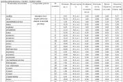
There is every reason to consider DLP technology promising and effective for foundry production, and not just for research and development. The time (taking into account the preparatory and final operations) for constructing the parts of the inlet pipe with a height of 32 mm and the receiver with a height of 100 mm is 1.5 and 5 hours, respectively. Whereas on a Viper SLA machine (3D Systems) of comparable size, such models would take ≥ 5.5 and 16 hours to build. Of interest are the machines of the Extrim and EXEDE series, which are positioned as AF machines for the serial production of master models and models for forest products. The peculiarity of these machines is that, unlike other technologies, they use not discrete (step-by-step) but continuous downward movement of the platform at low speed. Therefore, the models do not have pronounced steps characteristic of other construction methods. Models require post-processing - removal of supports and, in some cases, as in stereolithography - additional polymerization. The main characteristics of Envisiontec machines are shown in the table. A wide selection of materials for master models, burn-out models and vacuum-forming models (withstanding up to 150°C), conceptual modeling makes these machines especially attractive when it is necessary to produce a large number of models of a wide range. MJM (Multi Jet Modeling) technology for obtaining wax synthesis models. Models (Fig. 12) are built on 3D printers using special model material, in compound which includes a photosensitive resin - an acrylic-based photopolymer (binder) and foundry wax (50%). Using a multi-jet head, the material is applied layer by layer onto the working platform, each layer being cured by irradiation with an ultraviolet lamp.
The peculiarity of the technology is the presence of the so-called. supporting structures - supports to hold overhanging elements of the model during the construction process. The material is a wax polymer with a low melting point, which, after building the model, is removed with a stream of hot water.
The disadvantage of the technology is the relatively high cost of consumables - $300/kg; advantages - the speed of obtaining the model and, no less important, the high quality of the model material, from the point of view of the actual lost wax casting technology (molding, melting out the model).
| Dimensions of the construction area, mm | Construction layer thickness, mm | Dimensions, mm | Weight, kg | |
| Standard | 120´90´230 | 0.025¼0.150 | 480´730´1350 | |
| Zoom | 190´142´230 | |||
| Standard UV | 175´131´230 | |||
| Extreme | 320´240´430 | 0.025¼0.150 | 810´730´2200 | |
| EXEDE | 457´431´508 | 0.025¼0.150 | 810´840´2200 |
Casting polyurethane resins and wax into silicone molds. The second rapidly developing area of using photopolymers is the production of high-precision master models, both for subsequent production of wax models through silicone molds, and for polyurethane casting. The use of silicone molds is extremely effective when done individually and in small quantities. serial production wax models, while achieving their high quality.
Master models are usually grown on SLA or DPL installations, which provide the best surface finish and high accuracy of model construction. Models produced on 3D printers such as ProJet and Objet are also of fairly high quality.
 Rice. 13. Silicone mold (top), master model (bottom left), wax model (center), metal casting (right)
Master models are used to obtain the so-called. quick molds, in particular silicone ones (Fig. 13), into which polyurethane resins or wax are then poured for subsequent metal casting. Elastic mold casting technologies are widespread in world practice. Various silicones with a low shrinkage coefficient and relatively high strength and durability are used as mold materials (here silicone is a mixture of two initially liquid components A and B, which, when mixed in a certain proportion, polymerize and form a homogeneous, relatively solid mass).
Elastic molds are obtained by filling a master model with silicone in a vacuum, which is usually placed in a wooden flask; the flask is placed in a vacuum machine, where components A and B are first mixed in a special container, then the silicone is poured into the flask. Vacuum is used to remove air from liquid components and provide high quality molds and castings. After pouring for 20...40 minutes, the silicone polymerizes. The delivery package of equipment for vacuum casting, as a rule, includes the vacuum machine itself (one- or two-chamber) and two heating cabinets: for storing consumables at ~ 35°C and for holding molds at ~ 70°C; the latter is used for preliminary thermal preparation
silicone mold and casting materials immediately before pouring.
After pouring the polyurethane resin, the mold is returned to the oven to cure the resin. Therefore, the size of the second heating cabinet must correspond to the dimensions of the vacuum chamber of the machine. Using special techniques, the mold is cut into two or several parts, depending on the configuration of the model, then the model is removed from the mold.
The usual mold durability of 50...100 cycles is quite sufficient for the production of a pilot series of castings. These technologies have proven to be very effective for the production of pilot batches and small-scale products typical for the aviation, medical and instrument-making industries.
A wide range of both silicones and polyurethane resins makes it possible to produce castings with impact- and temperature-resistant properties, different hardnesses and a variety of colors. Modern enterprises that produce investment castings usually include technological equipment AF machine for growing master models and machine for vacuum casting into silicone molds.
M.A. Zlenko – Doctor of Technical Sciences, NIIMashTech ONTI SPbSPU.
P.V. Zabednov is an engineer at FSUE Vneshtekhnika.
1The method of obtaining master models (RP prototypes) by layer-by-layer synthesis for casting on burnt-out models using sterolithography using Digital Light Processing technology is considered. The possibility of obtaining models with an internal adjustable cellular structure in the form of a typical Wigner–Seitz unit cell has been determined. Envisiontec SI500 cross-linked photosensitive polymer was used as the starting material. In this work, a computer 3D model was designed in STL format and a prototype was obtained, which is a shell filled with an adjustable cellular structure. The optimal illumination modes and the thickness of the illuminated layer of the sample have been determined, with the help of which the dimensions of the bridges of the cellular structure can be adjusted. The presence in the model of a structure in the form of an array of cells will in the future make it possible to significantly reduce the volume of material used and reduce the pressure on the ceramic shell when it is removed.
digital light processing
synthesis models
cellular structure
photopolymer
master model
1. Vasiliev V.A., Morozov V.V. Production of steel castings using photopolymer models by burning them in a foundry mold / Int. NTK " Contemporary issues metallurgical production". Sat. work. - Volgograd. 2002. – pp. 336–337.
2. Vasiliev V.A., Morozov V.V., Shiganov I.N. Using methods of layer-by-layer formation of three-dimensional objects in foundry // Bulletin of mechanical engineering. 2001. - No. 2. - P. 4–11.
3. Evseev A.V. Operational formation of three-dimensional objects using laser stereo lithography [Text]/ A.V. Evseev, V.S. Kamaev, E.V. Kotsyuba and others // collection. proceedings of IPLIT RAS. – pp. 26–39.
4. Zlenko M.A. Additive technologies in mechanical engineering [ Electronic resource]: training manual for universities in the field of master's training " Technological machines and equipment” / M.A. Zlenko, A.A. Popovich, I.N. Mutylina. [SPb., 2013] URL: http://dl.unilib.neva.ru/dl/2/3548.pdf
5. Zlenko M. Rapid prototyping technologies - layer-by-layer synthesis of a physical copy based on a 3D CAD model // CAD/CAM/CAE Observer. 2003. No. 2 (11). pp. 2–9.
6. Skorodumov S.V. Technologies of layer-by-layer synthesis when creating three-dimensional models for blank production. // Bulletin of mechanical engineering. – 1998. – No. 1. – P. 20–25.
7. S.O. Onuh., Y.Y. Yusuf. Rapid prototyping technology: applications and benefits for rapid product development. // Journal of Intelligent Manufacturing. 1999. V. 10. PP. 301 – 311.
Modern three-dimensional computer design systems can significantly reduce the time and money spent on the development and design of new parts. The transition to digital product description - CAD and the resulting RP technologies (RP rapid prototyping technologies) have made a real revolution in foundry production, especially in high-tech industries - aviation and aerospace, nuclear industry, medicine and instrument making. traditional technologies, the use of new methods for producing foundry synthesis models through layer-by-layer synthesis technologies photopolymer material made it possible to radically reduce the time to create new products, improve the quality and accuracy of cast parts and reduce rejection.
The most widespread use of RP prototypes is as investment casting patterns in foundries to produce high-precision and geometrically complex metal castings. The use of RP models as burn-out models in casting processes makes it possible to obtain geometrically complex metal castings with an accuracy of at least 12 grades and surface roughness of 7Ra on average. However, the use of synthesis models (RP prototypes) is often accompanied by cracking and subsequent destruction of the casting mold at the stage of high-temperature removal of the model mass.
The main reason for the destruction of ceramic molds during the removal of the injection molding model is associated with the difference in the thermomechanical properties of the ceramic shell and the prototype material. One of the ways to reduce contact stresses between the casting model and the ceramic mold during thermal exposure is to replace the monolithic model with a model of an equivalent shape, which is a shell with a cellular filler of the internal cavity as a supporting frame that prevents the loss of stability of the shell from the effects of residual stresses. The design of such synthesis models includes the selection of the shape and geometric parameters of the cell, ensuring, on the one hand, a minimum level of contact stresses, and on the other, maintaining the specified accuracy parameters of the polymer model throughout the manufacturing and molding process.
The purpose of this work is to study the possibility of obtaining RP prototypes with an internal adjustable structure in the form of Wigner-Seitz type cells.
Materials and research methods
The starting material is Envisiontec SI500 cross-linked polymer, which is used in the stereolithography process. To obtain prototypes with an adjustable internal structure, this work used process sterolithography, the diagram of which is presented in Figure 1. The main difference from classical sterolithography is the departure from the use of a laser circuit to initiate the photopolymerization reaction and its replacement with several digital video projectors using Digital Light Processing (DLP) technology. The developer of this technology is Enviziontec (Germany). Acrylic photopolymer is used as the starting material to create the model. The essence of the process is to use a “mask” of each current section of the model, projected onto the working platform through a special system of very small mirrors using a spotlight (containing two lamps with high brightness of light). After illuminating the layer, the platform is lowered exactly to the thickness of the next layer into a bath of liquid polymer. The formation and exposure of each layer to visible light occurs relatively quickly. This explains the high speed of model construction (on average 1 cm per hour in height with a construction step of 50 μm).
Rice. 1. Scheme of operation of a stereolithographic machine using DLP technology: 1 - projector; 2 — photomask; 3 - polymer leveling mechanism; 4 - bath with liquid polymer; 5 - lowered base; 6 - model made of cured polymer
When using a step of 25 μm, the models have virtually no steps from the layers that are characteristic of all layer-by-layer synthesis technologies. This possibility allows us to obtain products with high surface quality with a roughness of up to Ra0.1 and dimensional accuracy of up to 0.1 mm.
Research results and discussion
To obtain prototypes with an internal adjustable structure, the Envisiontec Perfactory XEDE installation was used. Work was carried out to model a sample consisting of a shell with a wall thickness of 0.5 mm, filled with an adjustable cellular structure (Fig. 3). To fill the internal volume of the sample, an elementary Wigner-Seitz unit cell was used, which is an array in the STL file. The experiments were carried out at different parameters for the sample exposure time of each subsequent polymerizing layer, from 6.5 to 18 s.

Rice. 3. CAD model of a cube shell filled with a cellular structure
As a result of the work carried out, a prototype was obtained with a shell wall thickness of 0.5 mm, filled with a cellular structure made of photopolymer material SI500 (Fig. 4). The illumination time of each layer is 18 s (both the shell and the cellular structure with a jumper thickness of 0.5 mm).

Rice. 4. Prototype with an organized cellular structure
By varying the illumination parameters of the layer of polymerizing material, it is possible to obtain cells with a bridge thickness in the size range from 0.12 to 0.5 mm.
Conclusion
The technological possibility of developing a technology for producing complex geometric objects with an internal adjustable cellular structure has been established. Potential application of this technology is possible in foundry production, namely in burnout casting. By replacing the monolithic master model with a model representing a shell with an internal adjustable structure in the form of cells, it is possible to reduce the pressure of the burned-out model composition on the ceramic mold by selecting the thickness of the shell, the shape and size of the cells.
Reviewers:Sirotenko L.D., Doctor of Technical Sciences, Professor, Perm National Research Polytechnic University, Perm;
Khanov A.M., Doctor of Technical Sciences, Professor, Perm National Research Polytechnic University, Perm.
Colleagues, today we’ll talk about painful issues!
Namely, how some 3D printer sellers try to sell you their product by hook or by crook....
First, let's talk about the two most common 3D printing technologies: DLP and SLA, these are the most common 3D printers in dentistry.
In the dental market today, the most popular are printers using DLP and SLA printing technologies. What is the difference between these two technologies?
Both (DLP and SLA) use “liquid plastic” as raw materials for printing, in other words a photopolymer that polymerizes and takes on a solid form under the influence of UV radiation.
A little history:
Pioneers in the development of dental 3D printing and the creation of biocompatible polymers in large assortment, is a Dutch company Nextdent, previously known to everyone as the company Vertex.
This winter, seeing the great potential of these biocompatible materials, Nextdent was bought by the father of 3D printing, the 3D giant - the American company 3D Systems.
Obtaining certification for biocompatible materials is not so easy, so Nextdent's photopolymers are acquired by other companies and sold under their own different brands: Formlabs, Novux and others.
Now let's get back to 3D printing technologies.
DLP. Printing principle:
The program that comes with the printer splits the printed object into layers of a given thickness.
Photopolymer (printing material) is poured into a printer tray with a transparent bottom.
The work table is immersed at the very bottom of the bath, retreating from the bottom by one (first) layer of our object (in this “indentation” there is a liquid photopolymer).
A projector located under the bathtub projects the image of the first layer onto the bottom of the bathtub and, thanks to UV radiation, only the plastic that received the image from the projector hardens.
This is how our printed object grows layer by layer, be it a jaw model or a temporary crown. SLA. Printing principle: The printing principle is similar, but with the difference that not the entire layer is projected, but a laser beam quickly passes through each point of the object, which polymerizes the liquid photopolymer (material)

It is often not easy for a buyer to understand all the properties of a 3D printer and its materials on their own, but there is one clear indicator that almost everyone focuses on. And naturally, sellers of 3D printers mainly play on this indicator.
Have you already guessed what the main argument they give when selling you their printer?
Printing precision!
Let's then look at this popular parameter, which is twisted in one direction or another, intentionally or due to incompetence.
Printing accuracy.
This parameter depends on many factors, not only on the printer, but also on the material and the environment.
How does it depend on the material?
The more opaque the material (filled with pigments and light blockers), the more accurate the products printed from it will be. This occurs due to the absence of light scattering during printing and polymerization of the material adjacent to the model.
How does it depend on the environment?
When printing with photopolymer, it is important to control its temperature during printing.
During polymerization, DLP printers generate a lot of heat.
How does elevated temperature negatively affect printing?
Very simply, the chemical reaction accelerates and there is too much current light to polymerize the material.
The risk of polymerization of the boundary layer of the model increases (exposure of excess plastic) and, accordingly, an increase in its size, in other words, loss of accuracy.
In SLA printers this is not so scary, since the laser has lower power (generates less heat) and the volume of the material bath is usually much larger (than in DLP printers), which leads to the fact that the photopolymer in the bath heats up more slowly and there is no risk of overheating.
That is why SLA printing takes a little longer, but it does not have the risks of overheating and loss of accuracy, as in DLP printers.
This means that in order to get the most accurately printed product, and it’s hot in your room, control the temperature of the polymer used.
Cold is also not the best option, since the material may not have enough light intensity, it will not stick to the printing table and you will have to warm up the material and start the entire printing process from the beginning.
Of course, fiddling around with heating the material is not very convenient!
But if your printer has a function for automatically heating the material, you won’t have to tinker with it manually.
Many jewelers successfully use program-controlled milling machines in their work, which grind waxes for casting, and some machines even grind metal parts. In this article we will look at 3D printing as an alternative and complement to this process.
Speed
When creating a part in a single copy, a CNC milling machine wins in speed - the machine cutter moves at a speed of up to 2000-5000 mm/min, and where the router can handle it in 15 minutes, the printer can print a part for up to an hour and a half, sometimes even more.
This is true, however, only for simple and smooth products, such as a wedding ring of a simple shape and without a pattern, which do not require high quality surfaces, because They are easy to quickly polish. The router turns complex products as slowly as a 3D printer prints them, and often longer - processing time can reach up to six hours.

Photo @ FormlabsJp
When creating a series of products at once, the situation changes radically - in one pass, the printer is able to print a full platform of waxes - this is a platform (using the example of a printer) 145x145 mm, and depending on the size of the models, up to 35 pieces can be placed there. With a printing speed of 10-30 mm/hour (and it prints in layers, over the entire area of the platform at once), this gives a noticeable advantage over a milling cutter, which cuts out only one model at a time - this is either one complex part, or several simple, flat ones from one cylindrical wax blank.
In addition, a 3D printer can immediately print a tree of models for casting, without the need to assemble it from separate blanks. This also saves time.

Photo @ 3d_cast
Precision and quality
The positioning accuracy of the cutter in CNC machines reaches 0.001 mm, which is higher than that of a 3D printer. The quality of surface processing by a milling cutter also depends on the size of the cutter itself, and the radius of the tip of the cutter is at least 0.05 mm, but the movement of the cutter is programmed, usually a step of a third or half of the cutter, respectively - all transitions are smoothed out.

Photo @ freemanwax
The layer thickness when printing on Form 2, the most popular but far from the most accurate printer, and therefore the vertical accuracy, is 0.025 mm, which is half the diameter of the tip of any cutter. Its beam diameter is 0.14 mm, which reduces resolution but also produces a smoother surface.

Photo @ landofnaud
In general, the quality of the resulting products on a photopolymer printer and top-end milling machines is comparable. In some cases, on simple forms, the quality of the milled part will be higher. With the complexity of shapes, the story is different - a 3D printer is capable of printing something that no milling cutter could ever cut, due to design limitations.
Economical
Photopolymers used in stereolithography printers are more expensive than regular jewelry wax. Large pieces of wax after the milling machine can be melted into new blanks, although this is also time-consuming and unnecessary steps, but it also saves money. Milled wax is cheaper in terms of the cost of each individual product of the same volume.
Wax is not the only consumable material in the work of a router; the cutters also gradually wear down and require replacement; they last for 1-2 months of intensive work, but this does not significantly reduce the gap.
The work of a milling cutter, in terms of the cost of manufactured products, is cheaper.

Photo @ 3DHub.gr
Convenience and features
The specificity of milling is such that even on a five-axis machine the cutter can not reach everywhere. This forces jewelers to create composite models from several parts, which then must be soldered, or even pre-finished by hand. A 3D printer is capable of printing a model of any complex shape, including internal cavities and complex joints, in one pass.
How it happens
The printed models are soldered to a wax barrel, then the resulting structure is filled with plaster or a special solution, after which it hardens finished form It is heated in a furnace and then filled with metal.
The wax material burns out without a trace, allowing the metal to take up all the free space and exactly repeat the shape of the workpiece.
1. The casting process begins with printing the model and standard post-printing processing - the printed part is separated from the supports, washed, subjected to curing exposure in ultraviolet light, and, if necessary, lightly polished.


2. Next, the process is similar to that used for casting using conventional waxes. The blanks are soldered to a wax sprue, which will hold them in correct position and will create a channel for metal distribution.

If the quantity and size of the products allow, you can skip this step - if you print the products together with the sprue as a single unit.
3. The sprue is fixed in the injection flask. If the flask is perforated, the holes should be closed, for example, with packing tape.

4. The filling solution is mixed in the proportions specified by the manufacturer.

Then it is poured into a flask with a sprue inside. Pour carefully so as not to damage the model or dislodge the tree.

5. The flask is placed in a vacuum chamber for at least 90 seconds so that all the air comes out of the solution. Then it is transferred to a place protected from vibration to allow it to harden as quickly as possible.

6. Molded containers are placed in an oven, cold or heated to 167ºC, and the temperature is gradually raised until the plastic of the models is completely burned out.


Preheat - preheating.
Insert flask - place the flask in the oven.
Ramp - raise (change) the temperature.
Hold - hold the temperature (example: 3h = 3 hours)
7. Once this process is complete, the metal is poured into the mold.
8. After filling, the mold is cooled and the filling material is washed out.

9. All that remains is to extract finished goods, separate them and polish them slightly.


Conclusions:
Both technologies have their pros and cons. If the jewelry workshop already has a CNC milling machine, then it will cope with most of the tasks of producing single pieces. Moreover, if only single copies are made and not very often, then the machine wins in speed.
If the goal is not to develop production, increase the volume of work, turnover of funds, or raise the level of complexity of products, then a 3D printer will only be an additional financial burden.
With an increase in the pace and volume of work, with the constant introduction of new models, the advantages of a 3D printer will become noticeable immediately; in mass production, the difference in speed is serious. The printer can hardly be overestimated in rapid prototyping and production of batches of blanks.
If the enterprise carries out both types of orders - both single and serial - it will be more efficient and economically feasible to have both devices on the farm, for different types of work, they will organically complement each other.
Equipment

Technology: SLA
Working chamber: 145 x 145 x 175 mm
Layer thickness: 25-100 microns
Laser Focus: 140 µm
Beam power: 250 mW
Price: rub
The Form 2 is a compact stereolithography 3D printer that fits easily on your desktop.

Due to its accuracy (25-100 microns), it is very popular among orthodontists and jewelers, as it is capable of printing many products in one session.

Photo @ FormlabsJp
Photopolymer for printing burnt-out models costs rubles per 1-liter cartridge.

Technology: MJM
Working chamber: 295 x 211 x 142 mm
Resolution: 800 x 900 x 790 dpi
Layer thickness: 32 microns
Price: rubles
Multi-jet printer from 3D Systems, designed for printing injection molded blanks using VisiJet materials and functional parts using plastics.

MJP is inferior to stereolithography printers in compactness - it is much larger and cannot be placed on a desktop, but this is compensated by printing speed and a larger work area.

Technology: MJM
Working chamber: 298 x 183 x 203 mm
Resolution: up to 750 x 750 x 1600 DPI
Layer thickness from: from 16 microns
Printing accuracy: 10-50 microns
Price: rubles
The ProJet 3600W Max is an improved version of the ProJet 3500 CPX, a specialized 3D printer for printing injection molded waxes. These are industrial 3D printers used in production in continuous operation, with a large platform and high productivity. The printers in this series use Multi Jet Modeling (MJM) technology, which increases operating speed and allows the use of VisiJet materials specially designed for it.

The new wax used in it is highly durable; models made from it do not break in your hands when separated from the platform or accidentally dropped, which happened with models printed from its predecessor - Hi Cast.
The material costs rubles for 1.7 kg
RUB 275,000
Hunter is a new DLP 3D printer from Flashforge. DLP is a stereolithography technology that uses a projector instead of a laser.
This technology has its advantages - DLP printing is faster and can provide greater detail at ultra-small scales. On the other hand, a DLP projection consists of pixels; if a perfectly smooth surface is needed, it is better to choose an SLA printer, for example, Form 2.

Flashforge Hunter DLP 3D is compatible with third generation stereolithography resins, giving the user a wide choice of printing materials.

The printer uses a DLP module of the manufacturer’s own design, the characteristics of which are optimized specifically for 3D printing. This component has greater linear accuracy than conventional DLP designed for consumer video projectors.


Printing technology: DLP, 405nm
Maximum print speed: 30 mm/hour
Maximum print area: 120x68x200 mm
Resolution: 2560x1440 pixels per layer
Accuracy: 0.04mm
Layer thickness: 0.035-0.5mm
Weight: 12 kg
Price: rubles.
Wanhao Duplicator 7 is an inexpensive photopolymer printer for trying out stereolithography. The disadvantages of this model are low stability, low resolution and problems with repeatability out of the box.

Photo @

The person responsible for occupational safety and health (OHS) at work is a person specially trained for this purpose – an HSE engineer. He...
Reply from 02/03/2013 18:08 The transition to a new wage system (NSOT) did not entail timely development...
The production instructions must be clear, accurate and contain algorithms for actions in different situations in order...

Heavy engineering is a material-intensive industry with high metal consumption and relatively low...
Technical specialists provide a range of services through which companies and organizations help their clients...

The outline of the text is a consistent and coherent list of the main ideas that the author expresses in it. It is necessary...
The formula for product profitability on the balance sheet does not require data from Form No. 1 (balance sheet). All...

Signs about birds are so popular and there are so many of them that entire volumes are devoted to these superstitions. It's hard to collect them...

“What are your strengths and weaknesses?” - this is a question you will most likely be asked at any...
A bowhead, which had been stranded for more than a day, went to sea in the Khabarovsk Territory. A thirty-meter animal...

If you have children, then you, as parents, should know what the smallest bird in the world is. Of course it's...

Legal relations between employees and employers are established according to the Labor Code of the Russian Federation. But many people don't know how to do it...
An information letter is a non-commercial business letter, the main purpose of which is to inform...
Course work in the discipline “Economics of Organizations” “Forms of reproduction of fixed assets based on materials from OJSC...
Reply from 02/03/2013 18:08 The transition to a new wage system (NSOT) did not entail timely...
The production instructions must be clear, accurate and contain algorithms for actions in different situations...